ELECTRICAL
SYSTEM
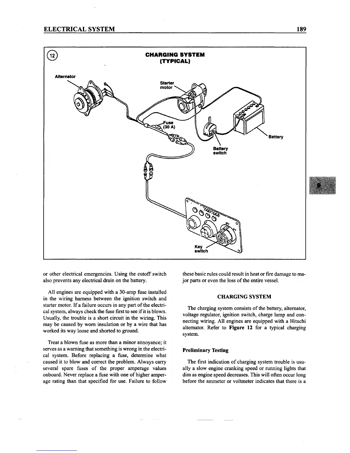
Alternator
CHARGING
SYSTEM
(TYPICAL)
189
Battery
or other electrical emergencies. Using the cutoff switch
also prevents any electrical drain on the battery.
All engines are equipped with a 30-amp fuse installed
in the wiring harness between the ignition switch and
starter motor.
If
a failure occurs in any part
of
the electri-
cal system, always check the fuse first to see
if
it is blown.
Usually, the trouble is a short circuit in the wiring. This
may be caused by worn insulation or by a wire that has
worked its way loose and shorted to ground.
Treat a blown fuse as more than a minor annoyance; it
serves as a warning that something is wrong inthe electri-
cal system. Before replacing a fuse, determine what
caused it to blow and correct the problem. Always carry
several spare fuses
of
the proper amperage values
onboard. Never replace a fuse with one
of
higher amper-
age rating than that specified for use. Failure to follow
these basic rules could result in heat or fire damage to ma-
jor
parts or even the loss
of
the entire vessel.
CHARGING SYSTEM
The charging system consists
of
the battery, alternator,
voltage regulator, ignition switch, charge lamp and con-
necting wiring. All engines are equipped with a Hitachi
alternator. Refer to
Figure 12 for a typical charging
system.
Preliminary Testing
The first indication
of
charging system trouble is usu-
ally a slow engine cranking speed or running lights that
dim as engine speed decreases. This will often occur long
before the ammeter or voltmeter indicates that there is a