208
14. Reassemble the shifter by reversing the disassembly
procedure. Note the following during reassembly:
a. Apply sealant to the detent setscrew threads.
b. Install the shift lever
on
the shift shaft while align-
ing the marks made during disassembly.
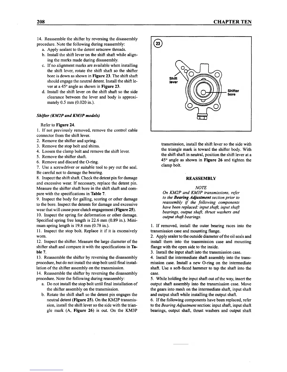
c.
If
no alignment marks are available
when
installing
the shift lever, rotate the shift shaft so the shifter
bore is
down
as shown in
Figure
23. The shift shaft
should engage the neutral detent. Install the shift le-
ver at a 45° angle as shown in
Figure
23.
d. Install the shift lever on the shift shaft so the side
clearance between the lever and
body
is approxi-
mately 0.5 mm (0.020 in.).
Shifter
(KM2P
and
KM3P
models)
Refer to
Figure
24.
1.
If
not previously removed, remove the control cable
connector from the shift lever.
2. Remove the shifter and spring.
3. Remove the stop bolt and shims.
4. Loosen the clamp bolt and remove the shift lever.
5. Remove the shifter shaft.
6. Remove and discard the O-ring.
7. Use a screwdriver or suitable tool to
pry
out
the seal.
Be careful not to damage the bearing.
8. Inspectthe shift shaft.
Check
the detent pin for damage
and excessive wear.
If
necessary, replace the detent pin.
Measure the shifter shaft bore in the shift shaft and com-
pare with the specifications in
Table
7.
9. Inspect the
body
for galling, scoring or other damage
to the bore. Inspect the detents for damage and excessive
wear
that will cause
poor
clutch engagement
(Figure
25).
10. Inspect the spring for deformation or other damage.
Specified spring free length is 22.6 mm (0.89 in.). Mini-
mum
spring length is 19.8
mm
(0.78 in.).
II.
Inspect the stop bolt. Replace it
if
it is excessively
worn.
12. Inspect the shifter. Measure the large diameter
of
the
shifter shaft and compare it with the specifications in Ta-
ble 7.
13. Reassemble the shifter by reversing the disassembly
procedure, but do not install the stop bolt until final instal-
lation
of
the shifter assembly on the transmission.
14. Reassemble the shifter by reversing the disassembly
procedure. Note the following during reassembly:
a. Do not install the stop bolt until final installation
of
the shifter assembly on the transmission.
b. Rotate the shift shaft so the detent pin engages the
neutral detent
(Figure
25). On the
KM2P
transmis-
sion, install the shift lever so the side with the trian-
gle
mark
(A,
Figure
26) is out. On. the
KM3P
CHAPTER
TEN
}--''I+~'+-_
Shifter
bore
transmission, install the shift lever so the side with
the triangle mark is toward the shifter body. With
the shift shaft in neutral, position the shift lever at a
45° angle as
shown
in
Figure
26 and tighten the
clamp bolt.
REASSEMBLY
NOTE
On KM2P
and
KM3P transmissions, refer
to the
Bearing
Adjustment
section prior to
reassembly
if
the following components
have been replaced: input shaft, input shaft
bearings, output shaft, thrust washers
and
output shaft bearings.
I.
If
removed, install the outer bearing races into the
transmission case and mounting flange.
2. Apply sealerto the outside diameter
of
the oil seals and
install them into the transmission case and mounting
flange with the open side to the inside.
3. Install the input shaft into the transmission case.
4. Install the intermediate shaft assembly into the trans-
mission case. Install a
new
O-ring on the intermediate
shaft. Use a soft-faced
hammer
to tap the shaft into the
case.
5. While holding the input shaft
out
of
the way, insert the
output shaft assembly into the transmission case. Move
the gears into
mesh
on the intermediate shaft, input shaft
and output shaft while installing the output shaft.
6.
Ifthe
following components have been replaced, refer
to the
BearingAdjustment section: input shaft, input shaft
bearings, output shaft, thrust washers and output shaft