COOLING
SYSTEM
SEAWATER
PUMP
(1GM
AND
1GM10
MODELS)
12
(J
10
11
~
II
173
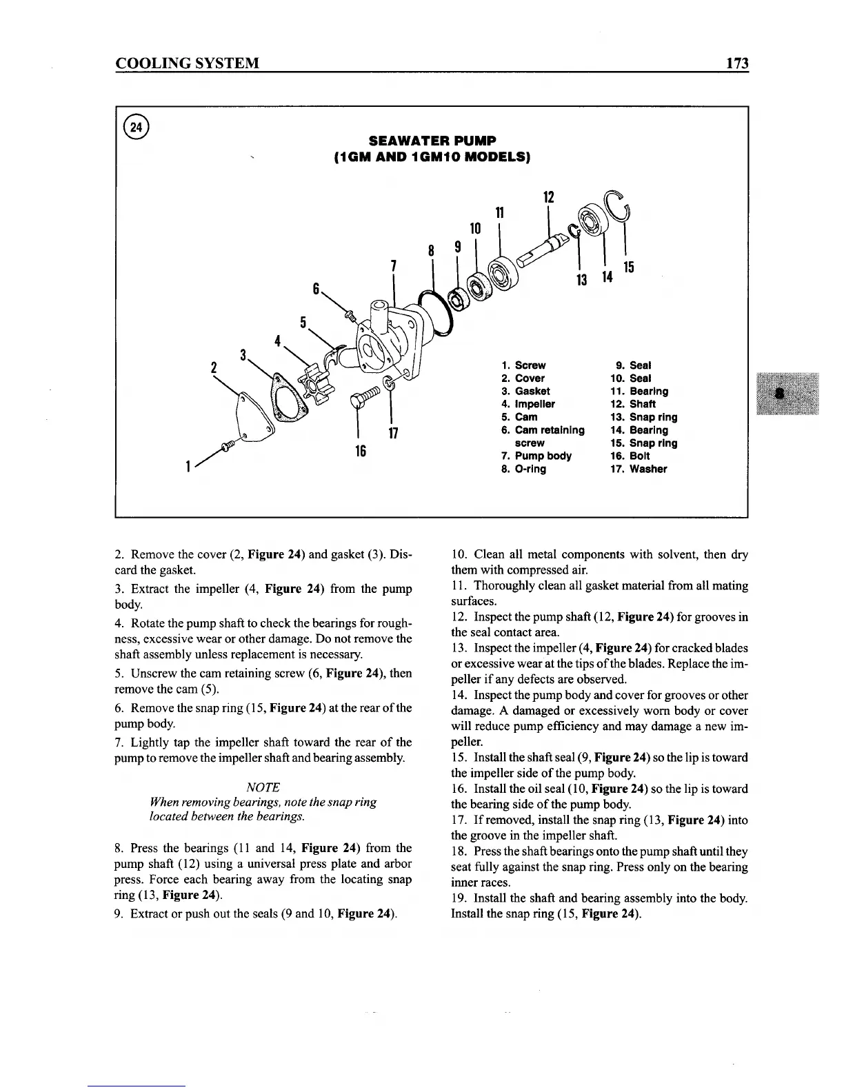
1. Screw
2. Cover
3. Gasket
4. Impeller
5. Cam
6. Cam retaining
screw
7. Pump body
8. Q-ring
9. Seal
10. Seal
11. Bearing
12. Shaft
13. Snap ring
14. Bearing
15. Snap ring
16.
Bolt
17. Washer
2. Remove the cover (2, Figure 24) and gasket (3). Dis-
card the gasket.
3. Extract the impeller (4,
Figure 24) from the pump
body.
4. Rotate the pump shaft to check the bearings for rough-
ness, excessive wear or other damage. Do not remove the
shaft assembly unless replacement is necessary.
5. Unscrew the cam retaining screw (6,
Figure 24), then
remove the cam (5).
6. Remove the snap ring (15,
Figure 24) at the rear
ofthe
pump body.
7. Lightly tap the impeller shaft toward the rear
of
the
pump to remove the impeller shaft and bearing assembly.
NOTE
When removing bearings, note the snap ring
located between the bearings.
8. Press the bearings (11 and 14, Figure 24) from the
pump shaft (12) using a universal press plate and arbor
press. Force each bearing away from the locating snap
ring (13,
Figure 24).
9. Extract or push out the seals (9 and 10,
Figure 24).
10. Clean all metal components with solvent, then dry
them with compressed air.
11. Thoroughly clean all gasket material from all mating
surfaces.
12. Inspect the pump shaft (12,
Figure 24) for grooves in
the seal contact area.
13. Inspect the impeller (4,
Figure 24) for cracked blades
or excessive wear at the tips
ofthe
blades. Replace the im-
peller if any defects are observed.
14. Inspect the pump body and cover for grooves or other
damage. A damaged or excessively worn body or cover
will reduce pump efficiency and may damage a new im-
peller.
15. Install the shaft seal (9,
Figure24) so the lip istoward
the impeller side
of
the pump body.
16. Install the oil seal (10,
Figure 24) so the lip is toward
the bearing side
of
the pump body.
17.
If
removed, install the snap ring (13, Figure 24) into
the groove in the impeller shaft.
18. Press the shaft bearings onto the pump shaft until they
seat fully against the snap ring. Press only on the bearing
inner races.
19. Install the shaft and bearing assembly into the body.
Install the snap ring (15,
Figure 24).