MULTICY
LIN
DER ENG INES
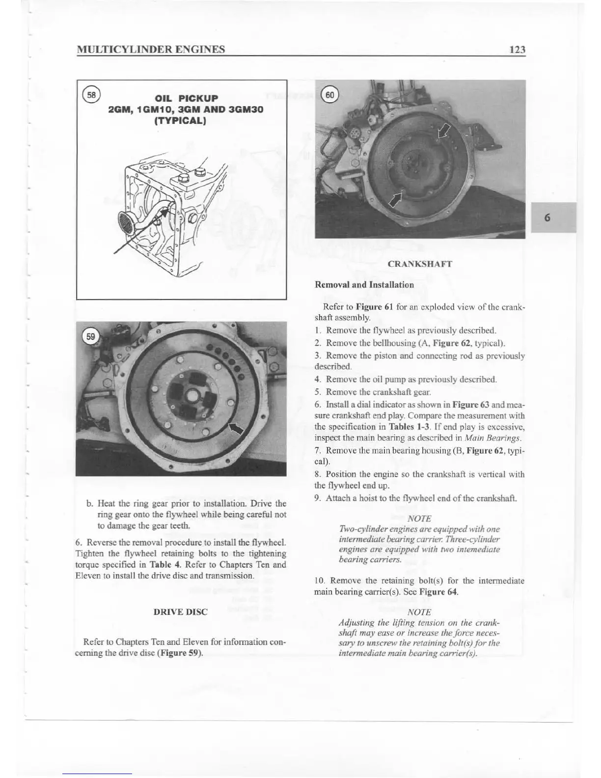
OIL
PICKUP
20M,
1GM10
,
3GM
AND
3GM30
(TYPICAL)
,
b. Heat the ring gear prior to installation. Drive the
ring gear onto the flywheel while being careful not
to
damag
e the gear teeth .
6. Reverse the removal procedure to install the flywheeL
Tighten the flywheel retaining bolts to the tightening
torque specified in T
ab
le 4.
Ref
er to Chapters Ten and
Eleven to install the drive disc and transmission.
DRIVE DISC
Refer to Chapters Ten and Eleven for information con-
cerning the drive disc (Figure 59).
123
CRA:\"KS
IIAFT
Removal lind Ins
tallati
on
Refer to Ffgure 61 for an exploded view of the
crank-
shaft assembly.
I. Remove the flywheel as previously described.
2. Remove the bellhousing (A, Figure 62. typical).
3. Remove the piston and connecting rod as previously
described.
4. Remove the oil pum p as previously described.
5. Remove the
crankshaft:
gea
r.
6. Install a dial indicator as shown in
Fi
gure
63 and mea-
sure cranksh
aft:
end play. Compare the measurement with
the specification in
Tables 1·3. If end play is excessive.
inspect the main bearing as described in
Main Bearings.
7. Remove the main bearing housing (B, Figure 62, typi-
cal).
8. Position the engine so the cranksha
ft:
is vertic al with
the flywheel end up.
9.
Attach a hoist to the flywheel end
of
the crankshaft.
NOTE
Two-cylinder engines are equippedwith one
intermediate bearing carrier. Three-cylinder
engines are equipped with two intemediate
bearing carriers.
10. Remove the retaining bolt(s) for the intermediate
main bearing carrier(s). See Figure 64.
NOTE
Adjusting the lifting tension on the crank-
shaft may ease or increase the force neces-
sary to unscrew the retaining boll(s)
for
the
intermediate main bearing
camerts).
6