190
potential problem. When charging system trouble is first
suspected. pe
rfonn
the following:
1. Check the alternator drive belt for correct tension
(Chapter
Thr
ee).
2. Check the battery to make sure
it is in satisfactory con-
dition and fully charged and thai all connections arc clean
and secure.
3.
Che
ck all connections at the alternator 10 make sure
they are clean
and
secure.
4.
Ifth
c charging system is nor performing as it should
af
-
ter each
of
the abov e points has been carefully checked
and any unsatisfactory conditions corrected. refer to
Chapter Two
and
perfo
nn
the Charging System Tests.
Alt
ern
ato r R
emovat/l
nstaltatton
This section provides alternator replacement proce-
dures. Com plete alternator overhaul is not practical for
the home mechanic. In some cases. replac
ement
parts are
unavailable.
This procedure is generalized to cover all applications.
Access to the alternator is quite limited in some engine
compartments and ca re should
be taken to avoid personal
injury,
I . Disconnect the negative battery cable.
2. Disconnect all wiring harnesses and leads at the rear
of
the alternator. See Figu re 13. typical.
NOTE
Whell loosening the retaining nut on an al-
temator
terminal, hold the terminal with a
wrench
to
prevent the terminal from rotat-
ing
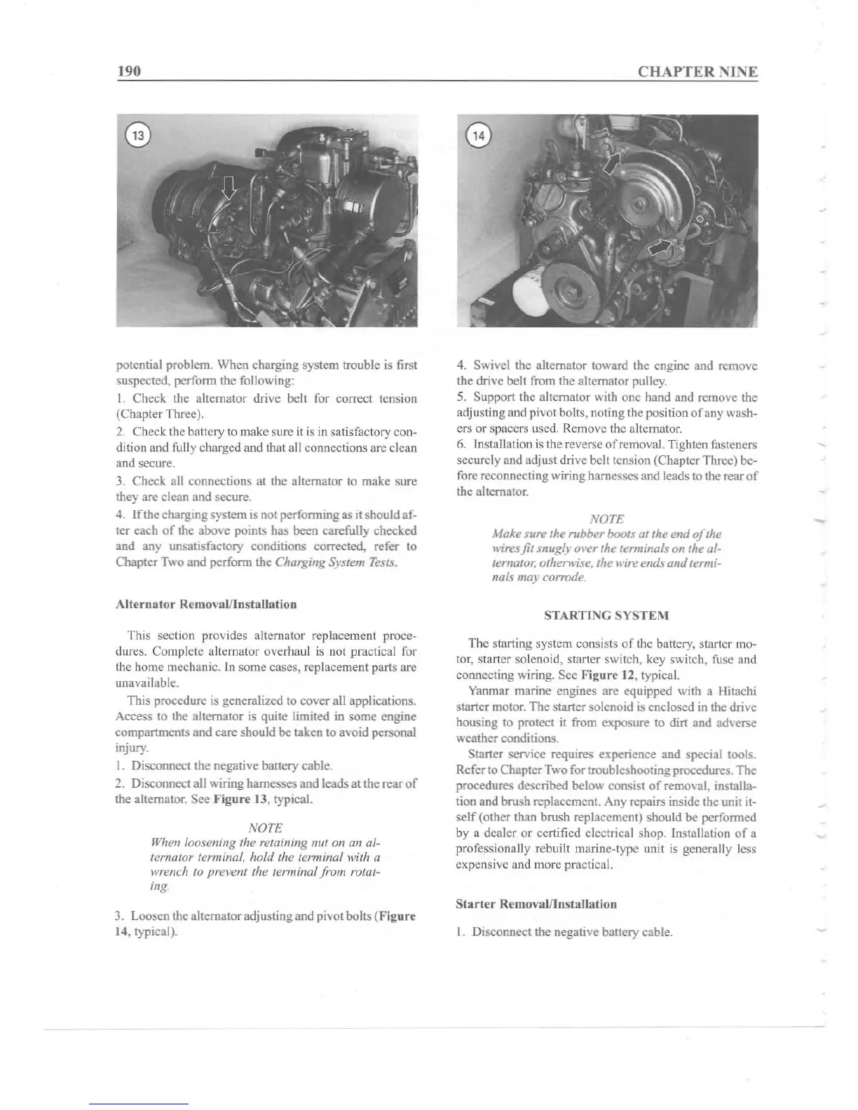
3. Loosen the alternatoradjusting and pivot bolts (Figure
14. typical).
C
HA
PTE R N
INE
4. Swivel the alternator toward the engine and remove
the drive
belt from the alternator pulley.
5. Support the alternator with
one
hand and remove the
adjusting and pivot bolts. noting the position
of
any wash-
ers or spacers used. Remove the alternator.
6. Installation is the reverse of removal. Tighten fasteners
secure ly and adjust drive belt tension (Chapter
Thr
ee) be-
fore reconnecting wiring harnesses and leads to the rearof
the alternator.
NOTE
Make sure the rubber boats at the
end
of
the
wires
fi
l snuglyoverthe terminals on the al-
ternator;otherwise, the wire
end
..
and
termi-
nal.
s may corrode.
STAR
Tl
I\G S
YSTE
M
The starting system consists
of
the battery, starter mo-
tor, starter solenoid. starter switch, key switc h, fuse and
connecting wiring. Sec Fi
gur
e 12, typical.
Yanmar marine engines are equ ipped
with a Hitachi
starter m
otor
. The starter solenoid is enclosed in the drive
housing to protect it from exposure to dirt and adverse
weather
co
nditions,
Starter service requ ires experience and special tools.
Refer to Chapter Two for troubleshooti ng procedu res. The
procedures described below consist of re
mova
l, installa-
tion and brush replacement. Any repairs
inside the unit it-
self
(other than brush replacement) should be
perf
ormed
by a dea ler
or
certified electrical shop. Installation
of
a
pr
of
essionally rebu ilt marine-type unit is gene rally less
expensive and more practical.
Starter
Removal/Ins
tallation
I. Disconnect the negative battery cable.
-