Note
Avoid splashing the flexible mount with water, oil etc.
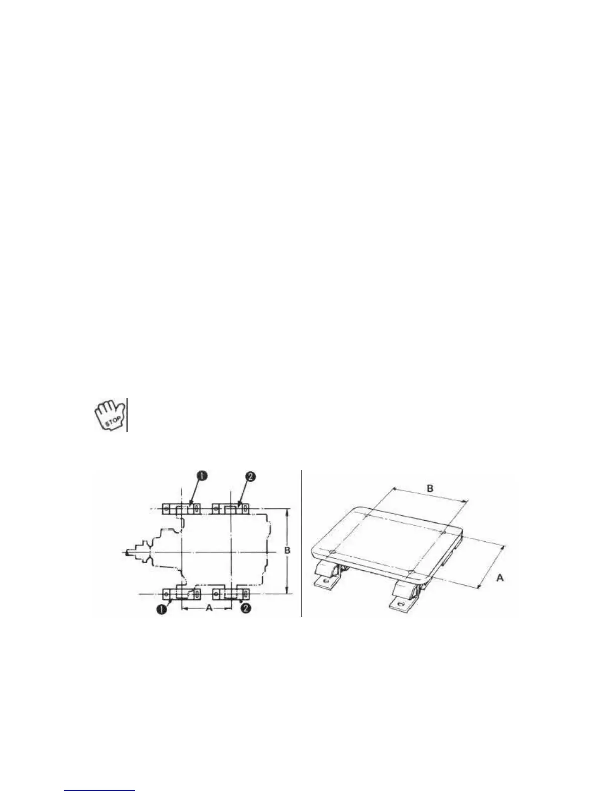
Indication # Installation distance (unit: mm)
Engine model
Front Rear A B
1GM 70 50 209 370
2GM 100 75 275 370
3GMD 100 75 355 370
3HM 100 100 432 400
It is convenient for installation to make the GUIDE PLATE as illustrated.
2) Be sure the propeller shaft lines up with and matches both shaft joints. If necessary adjust the
height of the engine with a jack nut to line up the propeller shaft and the engine. Fit the propeller
shaft and the intermediate shaft if there is one-to the engine.
With a gap gauge, measure the gap of the connection at the top, bottom, right, and left. The
maximum tolerance should be less than 0.2mm. Lock nut should be as low as possible.
3) Tighten the installation bolts firmly and evenly. Do not force the bolts in if the propeller shaft
does not line up.
Important
After 50 hours operation, check that the propeller shaft lines up again, and re-
adjust if necessary.
View From Top
1 - Rear 2 - Front
 Loading...