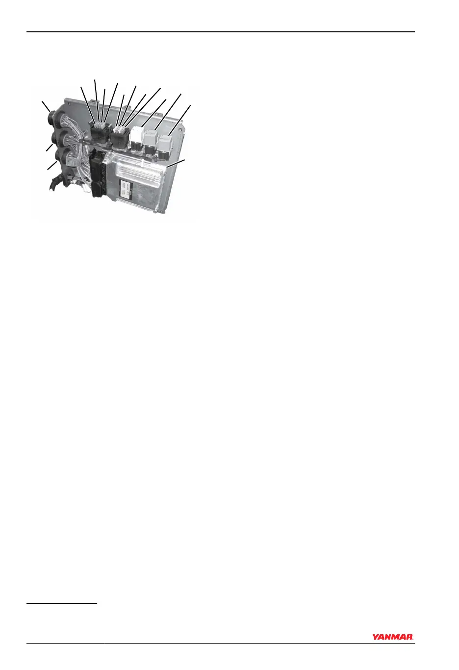
FUSES AND RELAYS
0004043
(1)
(2)
(3)
(4)
(5)
(6)
(9)
(10)
(11)
(12)
(13)
(14)
(15)
(7)
(8)
Figure 10
1 – Fuse F1 (3 A) - CAN Switched
Power
2 –
Fuse F2 (10 A) - Ignition
*
3 – Fuse F3 (15 A) - Fuel Supply
Pump
4 – Fuse F4 (30 A) - ECU Switched
Power
5 – Fuse F5 (20 A) - Power to Sensors
and Actuators
6 – Fuse F6 (10 A) - Auxiliary Power
7 – Jumper Fuse F7 (3 A) - Single /
Port Selection, default is single /
port (fuse in). Remove fuse for
starboard configuration.
8 – Jumper Fuse F8 (3 A) - CAN /
Analog Throttle Selection,
default is analog (fuse out).
Insert 3 A fuse to configure for
CAN.
9 – K1 - Starter Relay
10–K3 - Fuel Supply Pump Relay
11–K2 - Main Power Relay
12–ECU
13–Connector X1 - Communication
to Helm Display
14–Connector X21/1 - Engine Wiring
Harness
15–Connector X22/1 - Fuel Injector
Wiring Harness
To access the fuse and relay panel, remove
the four bolts from the E-Box cover and
remove cover.
NOTICE: The electrical panel cables must
be connected directly to the battery, and
must have a circuit breaker installed in the B
+ (red) lead.
* NEVER connect any additional devices to F2. F6 may be used however, it is not switched.
PRODUCT OVERVIEW
18 BY Series Operation Manual
© 2008 Yanmar Marine International