ELECTRICAL AND ECU
12-10
BY Service Manual
Function Description - Engine Management System
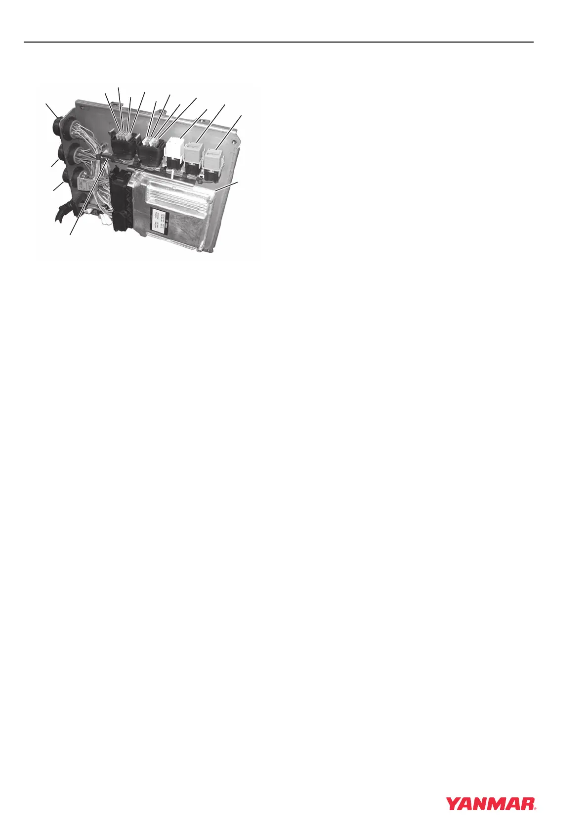
Electrical Panel Components
Figure 12-3
1 – Fuse F1 (3 A) - Switched B+ to CAN
2 – Fuse F2 (10 A) - B+ to Key Switch
3 – Fuse F3 (10 A) - Fuel Supply Pump
4 – Fuse F4 (30 A) - Switched B+ to ECU
5 – Fuse F5 (20 A) - Power to Sensors and
Actuators
6 – Fuse F6 (10 A) - Auxiliary Power
7 – Jumper Fuse F7 (3 A) - Single / Starboard
Selection
8 – Jumper Fuse F8 (3 A) - CAN / Analog
Throttle Selection
9 – K1 - Starter Relay
10 – K3 - Fuel Supply Pump Relay
11 – K2 - Main Power Relay
12 – ECU
13 – Connector X1 - Communication to Helm
Display
14 – Connector X21/1 - Engine Wiring Harness
15 – Connector X22/1 - Fuel Injector Wiring
Harness
16 – Blocking Diode V1
IMPORTANT
The electrical panel cables must be
connected directly to the battery, and must
have an 80 A circuit breaker installed in the
B+ (red) lead.
0003372
(
1
)
(
2
)
(
3
)
(
4
)
(
5
)
(
6
)
(
9
)
(
10
)
(
11
)
(
12
)
13
)
(
14
)
(
15
)
(
16
)
(
7
)
(
8
)