14 support@yardistrystructures.com
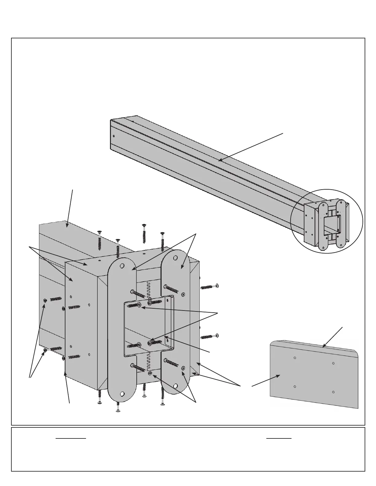
Step 2: Post Assemblies
HardwareWood Parts
Fig. 2.1
A: At the bottom of one (324) 7 x 7 Post place two Post Mounts tight to the bottom and inside faces as shown in
g. 2.1 and 2.2. Attach with two #10 x 1-1/4” Pan Screws per mount from the inside and two #8 x 2-1/2” Wood
Screws per bracket from the outside.
B: Place one (329) Plinth ush to the bottom and tight to the Post Mounts on each side of the (324) 7 x 7 Post
and attach with four #8 x 1-1/2” Wood Screws per plinth. Rounded edges on top. (g. 2.1, 2.2 and 2.3)
C: Repeat Steps A and B three more times to make four Post Assemblies.
(329)
Plinth
Tight
4 x (324) 7 x 7 Post 177.8 x 177.8 x 2387.6 mm (7 x 7 x 94”)
16 x (329) Plinth 23.8 x 133.4 x 225.4 mm (5/4 x 6 x 8-7/8”)
16 x #10 x 1-1/4” Pan Screw
16 x #8 x 2-1/2” Wood Screw
64 x #8 x 1-1/2” Wood Screw
8 x Post Mount
Top
Bottom
#8 x 2-1/2” Wood Screws
(x 2 per Post Mount, from
outside)
#8 x 1-1/2”
Wood Screws
(x 4 per Plinth)
(324) 7 x 7 Post
Post
Mount
(324) 7 x 7 Post
Fig. 2.2
(329)
Plinth
#10 x 1-1/4” Pan Screws
(x 2 per Post Mount, from
inside)
Rounded
Edge on Top
Fig. 2.3
Rounded
Edge on Top