32
3.4 WIRING PRECAUTIONS
(1) Wiring Leading-in Method
Lead in the wire through the knockout hole on the unit bottom. Since the
knockout hole is provided with a rubber bush, cut the rubber bush central
crosswise with a blade and lead the wire through.
(2) Separation from Signal Lines
Since strong noise component is superimposed on the braking resistor unit
and braking unit wiring, separate the units from signal lines which are weak
against noise.
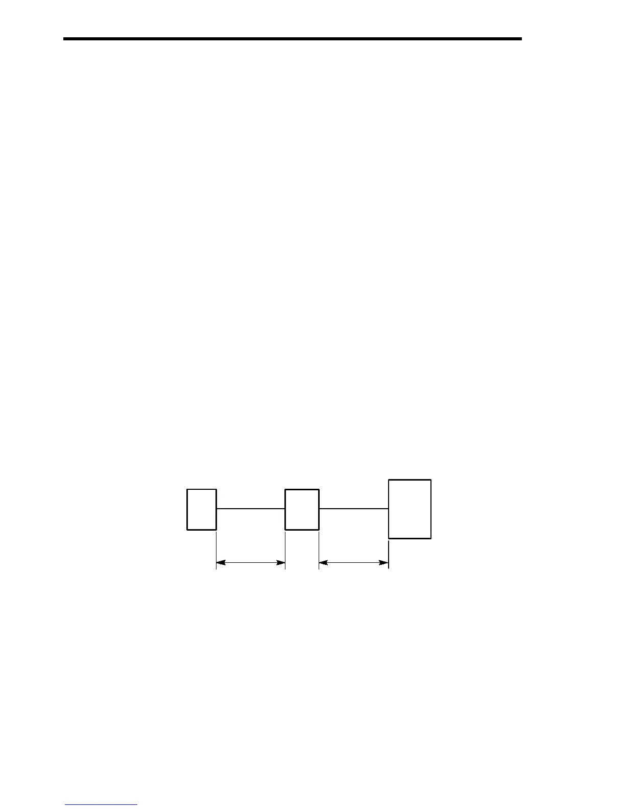
(3) Wiring Distance
• Wiring distance between the braking resistor unit and braking unit or
braking unit and inverter must be provided as shown in Fig. 13. Make
sure to bundle the wires between the units.
• When connecting two or more braking units in parallel, refer to 4.4,
“Parallel Connection of Braking Unit” for details.
Fig. 13 Wiring Distance