U (T1)
V (T2)
W(T3)
MC
S
T
THRX
THRX
OFF
ON
MC
SA
1
2
MC
TRX
TRX
18
20
SA
SA
IM
123
P
0
0
1
2
3
4
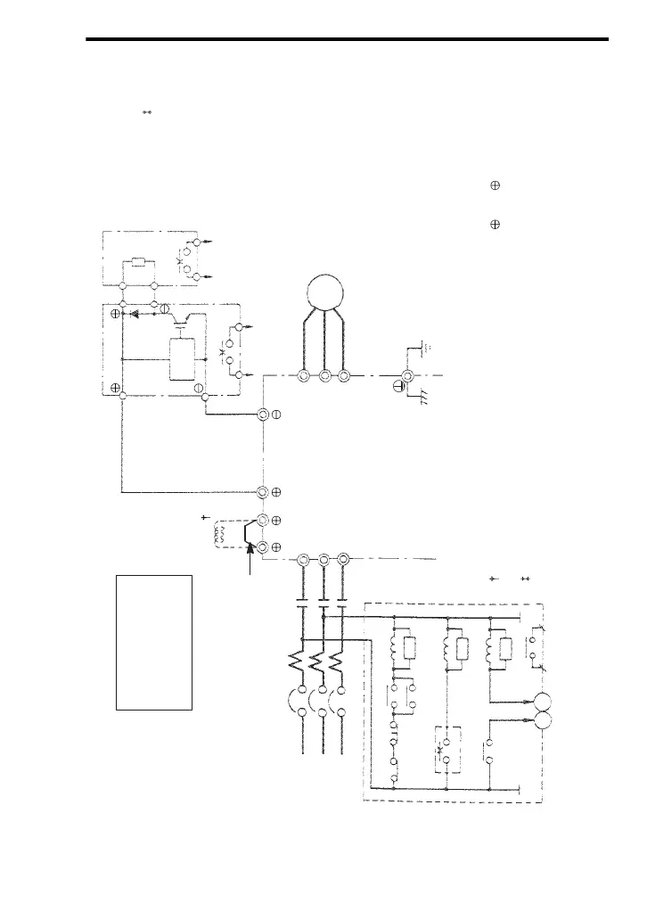
VS−616G5
MC
≈
≈
Motor
Braking Resistor Unit
L1 (R)
L2 (S)
L3 (T)
Overload Relay Trip Contact
of Braking Resistor Unit
Fault
Contact
MCCB
Overload Relay Trip Contact
DC Reactor
(Option)
Level
Detection
Braking Unit
R
B
3−Phase
Power Supply
200 to 230 V
50/60 Hz
Short−circuit
Bar
Ground (200V Class : 100Ω or less
400V Class : 10Ω or less)
∗∗
Where is “E” or “V”.
When installing a DC reactor (option), remove the common bar between 1 and 2 terminals
(provided as standard) and connect a DC reactor with the terminals.
When using the braking resistor unit, set constant L3−04 to “0” (stall prevention selection during
decel is disabled). If it is not changed, the inverter may not stop within set decel time.
Use sequencer to break
power supply side on over-
load relay trip contact of
braking resistor unit.
Failure to observe this can
result in a fire.