EasyManua.ls Logo

YASKAWA CH700 - Page 39

YASKAWA CH700
42 pages
To Next Page IconTo Next Page
To Previous Page IconTo Previous Page
Loading...
39
YASKAWA AC Drive
CH700
Catalog
KAEP C710617 24
YASKAWA
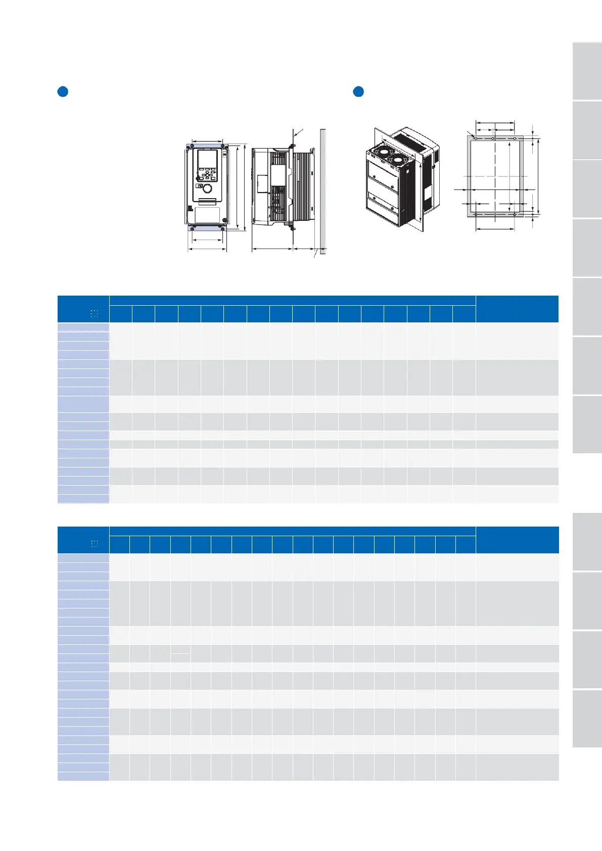
Heatsink External Mounting Kit Panel Modification for
External Heatsink
When the heatsink is installed
outside the drive, additional
W2
attachments are required.
Additional attachments are not
required for models CH70A2088
and above, and CH70A4060 and
above because installing a
heatsink outside the drive can be
performed on these models by
replacing their standard
mounting feet.
Contact Yaskawa if an instruction
Mounting
surface
manual is needed.
200 V Class
5 mm min.
Panel cut out dimensions
Note
:
The shaded area is the size when in installing the
gasket. Guarantee a wider and higher gasket
width space than the following W and H
information.
400 V Class
Catalog Code
CH7
0
A
Exterior and Mounting Dimensions and Cut
-
out Dimensions mm
Attachment for External
Heatsink
Model
(
Code No.
)
W
H
D1
D2
W1
W2
W3
W4
W5
W6
H1
H2
H3
H4
H5
A
B
d
1
4002
140
294
138
38
102
102
16
3
282
23
6
26
6
134
233
M
5
900
-
193
-
209
-
001
(
100
-
203
-
229
)
4003
4005
4006
140
294
138
73
102
102
16
3
282
23
6
26
6
134
233
M
5
900
-
193
-
209
-
001
(
100
-
203
-
229
)
4007
4009
4015
4018
4024
180
329
134
68
140
140
17
3
318
23.5
5
24.5
6
174
270
M
5
900
-
193
-
209
-
002
(
100
-
203
-
230
)
4031
4039
220
384
140
87
192
192
11
3
371
27
7
25
6
214
319
M
6
900
-
193
-
209
-
003
(
100
-
203
-
231
)
4045
106
4060
240
400
166
114
195
204
14.5
8
385
19.5
7.5
19.5
7.5
224
346
M
6
4075
255
450
166
114
170
210
34.5
8
436
20
8
20
6
239
396
M
6
4091
4112
264
543
186
149
190
220
29
8
527
19.5
8.5
20.5
7.5
248
487
M
8
4150
4180
312
700
260
160
218
263
39
8
675
33
12
32
13
296
610
M10
4216
4260
4304
440
800
254
218
370
310
23
12
773
31.5
14
31.5
13
416
710
M12
4371
4414
510
1140
260
220
450
404
18
12
179
225
1110
34
15
34
15
486
1042
M12
4453
4605
Catalog Code
CH7
0
A
Exterior and Mounting Dimensions and Cut
-
out Dimensions mm
Attachment for External
Heatsink
Model
(
Code No.
)
W
H
D1
D2
W1
W2
W3
W4
H1
H2
H3
H4
H5
A
B
d
1
2003
140
294
138
38
102
102
16
3
282
23
6
26
6
134
233
M
5
900
-
193
-
209
-
001
(
100
-
203
-
229
)
2005
2008
2011
2014
140
294
138
73
102
102
16
3
282
23
6
26
6
134
233
M
5
900
-
193
-
209
-
001
(
100
-
203
-
229
)
2018
2025
2033
2047
180
329
134
68
140
140
17
3
318
23.5
5
24.5
6
174
270
M
5
900
-
193
-
209
-
002
(
100
-
203
-
230
)
2060
220
384
140
87
192
192
11
3
371
27
7
25
6
214
319
M
6
900
-
193
-
209
-
003
(
100
-
203
-
231
)
2075
2088
240
400
166
114
195
204
14.5
8
385
19.5
7.5
19.5
7.5
224
346
M
6
2115
255
450
166
114
170
210
34.5
8
436
20
8
20
6
239
396
M
6
2145
264
543
186
149
190
220
29
8
527
19.5
8.5
20.5
7.5
248
487
M
8
2180
2215
312
700
260
160
218
263
39
8
675
33
12
32
13
296
610
M10
2283
2346
440
800
254
218
370
310
23
12
773
31.5
14
31.5
13
416
710
M12
2415
D1
D2
W1
W
Drill
A
W2
hole
×
4
(
d1
) W5
a
a
W4
W4
a
1
W
a
W3
W3
A
W6
H1
H
Wall
B
B
H2
H3
H5
H4
H1
Model Number/
Catalog Code /
Selecting
the Capacity
Peripheral
Devices
and Options
Terminal
Standard
Standard
Basic
Instructions
Dimensions
Features
Specifications
Connection
Diagram
Specifications

Related product manuals