13 Troubleshooting
YASKAWA TOEPC71061723A YASKAWA AC Drive CR700 Quick Start Guide 63
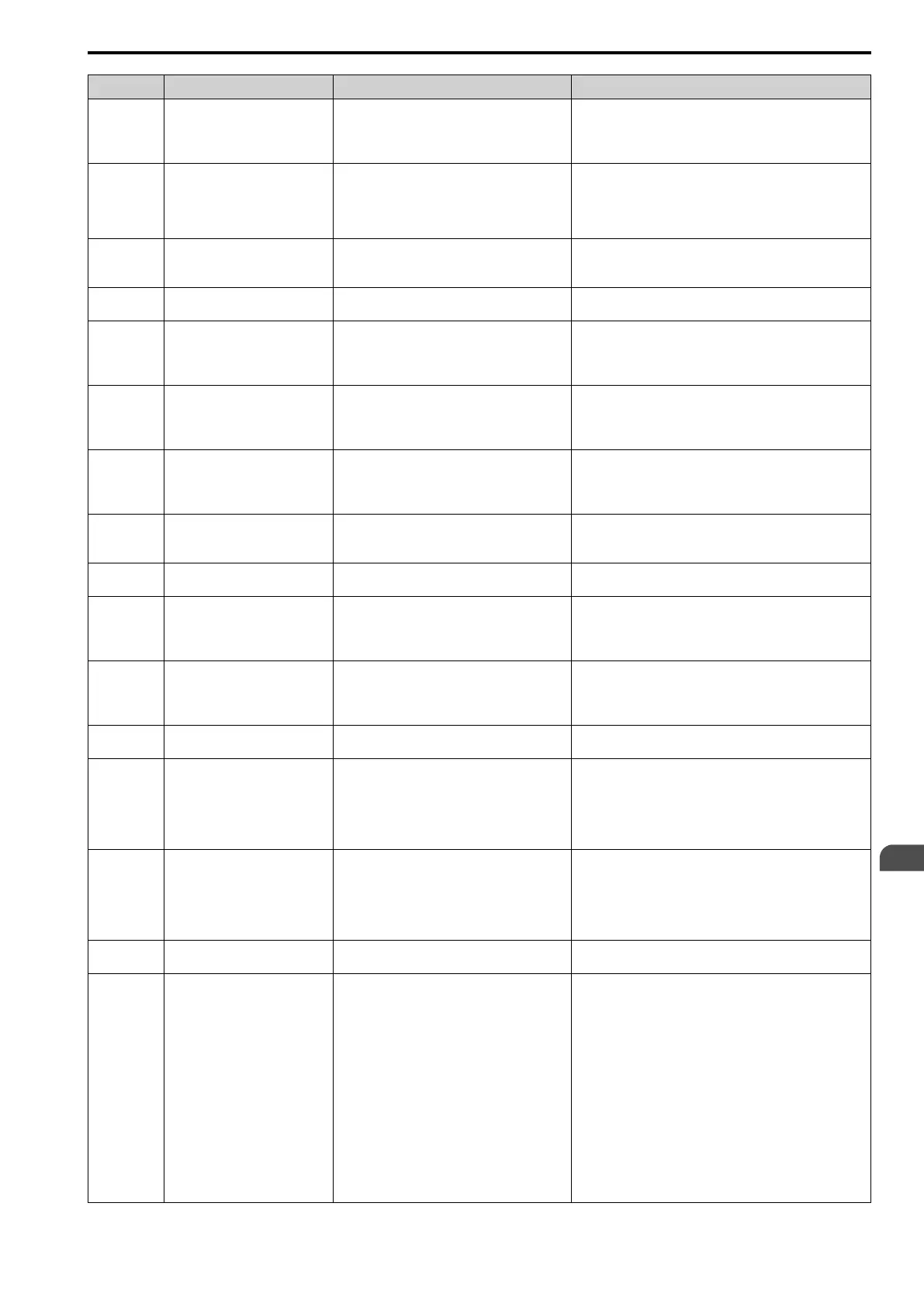
Code Name Causes Possible Solutions
oFA30 to
oFA43
Communication Option Card
Connection Error (CN5-A)
A fault occurred in the option card. 1. De-energize the drive.
2. Make sure that the option card is correctly connected to the
connector.
3. If the problem continues, replace the option card.
oFb00 Option Not Compatible with Port
The option connected to connector CN5-B is not
compatible.
Connect the option to the correct connector.
Note:
DO-A3, AO-A3, PG-B3, and PG-X3 options can connect to
connector CN5-B. To connect only one PG option card, use
the CN5-C connector.
oFb01 Option Fault/Connection Error
The option card connected to connector CN5-B was
changed during operation.
1. De-energize the drive.
2. Refer to the option card manual and correctly connect the
option card to the connector on the drive.
oFb02 Duplicate Options
The same option cards or the same type of option
cards are connected to connectors CN5-A, B, and C.
Connect the option card to the correct connector.
oFb03 to
oFb11
Option Card Error Occurred at
Option Port CN5-B
A fault occurred in the option card. 1. De-energize the drive.
2. Make sure that the option card is correctly connected to the
connector.
3. If the problem continues, replace the option card.
oFb12 to
oFb17
Option Card Error Occurred at
Option Port CN5-B
A fault occurred in the option card. 1. De-energize the drive.
2. Make sure that the option card is correctly connected to the
connector.
3. If the problem continues, replace the option card.
oFC00 Option Not Compatible with Port
The option connected to connector CN5-C is not
compatible.
Connect the option to the correct connector.
Note:
AI-A3, DI-A3, and communication options cannot be
connected to the CN5-C connector.
oFC01 Option Fault/Connection Error
The option card connected to connector CN5-C was
changed during operation.
1. De-energize the drive.
2. Refer to the option card manual and correctly connect the
option card to the connector on the drive.
oFC02 Duplicate Options
The same option cards or the same type of option
cards are connected to connectors CN5-A, B, and C.
Connect the option card to the correct connector.
oFC03 to
oFC11
Option Card Error Occurred at
Option Port CN5-C
A fault occurred in the option card. 1. De-energize the drive.
2. Make sure that the option card is correctly connected to the
connector.
3. If the problem continues, replace the option card.
oFC12 to
oFC17
Option Card Error Occurred at
Option Port CN5-C
A fault occurred in the option card. 1. De-energize the drive.
2. Make sure that the option card is correctly connected to the
connector.
3. If the problem continues, replace the option card.
oFC50 to
oFC55
Option Card Error Occurred at
Option Port CN5-C
A fault occurred in the option card. Refer to the manual for the PG-RT3 option card.
oH Heatsink Overheat
The ambient temperature is high and the heatsink
temperature of the drive is more than the value set
in L8-02 [Overheat Alarm Level].
• Measure the ambient temperature.
• Increase the airflow in the control panel.
• Install a cooling device (cooling fan or air conditioner) to
lower the ambient temperature.
• Remove objects near the drive that are producing too much
heat.
oH1 Heatsink Overheat
The ambient temperature is high and the heatsink
temperature of the drive is more than the oH1
detection level.
• Measure the ambient temperature.
• Increase the airflow in the control panel.
• Install a cooling device (cooling fan or air conditioner) to
lower the ambient temperature.
• Remove objects near the drive that are producing too much
heat.
oH3 Motor Overheat (PTC Input)
The thermistor wiring that detects motor
temperature is defective.
Correct wiring errors.
oH4 Motor Overheat Fault (PTC Input)
The motor has overheated. • Examine the load level, acceleration/deceleration times, and
motor start/stop frequency (cycle time).
• Decrease the load.
• Increase the values set in C1-01 to C1-08 [Acceleration/
Deceleration Time].
• Set E2-01 [Motor Rated Current (FLA)] correctly to the value
specified by the motor nameplate.
• Make sure that the motor cooling system is operating correctly,
and repair or replace it if it is damaged.
• Adjust E1-04 to E1-10 [V/f Pattern Parameters]. For motor 2,
adjust E3-xx [V/f Pattern for Motor 2] settings. For motor 3,
adjust E7-xx [V/f Pattern for Motor 3] settings. Decrease the
values set in Ex-08 [Mid Point A Voltage] and Ex-10
[Minimum Output Voltage].
Note:
If Ex-08 and Ex-10 are set too low, the overload tolerance will
decrease at low speeds.
EN
 Loading...


