Do you have a question about the YASKAWA V1000 MMD and is the answer not in the manual?
Key safety guidelines for operating the drive.
Specific hazards and precautions related to electrical shock and safe operation.
Important notices regarding equipment handling and protection procedures.
CE Low Voltage Directive compliance and safe disable function usage.
Checks after receiving the drive and recommended installation conditions.
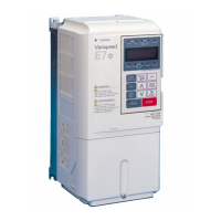
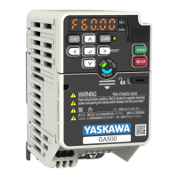
Technical specifications detailing the physical size of the drive unit.
Step-by-step instructions for mounting the drive onto a motor.
Step-by-step instructions for mounting the drive onto a wall.
Guidelines for main circuit wiring, input fuse selection.
Precautions and details for wiring the control circuits of the drive.
Considerations for output wiring, ground connection, and safety.
Arrangement and function of control circuit terminals and DIP switches.
Description of the drive's operator panel, LEDs, and function keys.
Explanation of the meaning of different LED indicators on the drive.
Overview of the drive's menu hierarchy and operational modes.
Step-by-step guide to configure and prepare the drive for operation.
Procedures for power-on checks and setting motor parameters.
Setting reference sources, I/O, and performing test runs for the drive.
Parameters for initial setup, operation modes, and DC injection braking.
Settings for acceleration, deceleration, torque compensation, and stall prevention.
Configuration for analog/digital I/O, monitoring, and motor control parameters.
Overview of drive faults and alarms, and how to reset them.
Detailed list of common drive faults, their causes, and corrective actions.
Guidance on resolving operator programming (OPE) and STO errors.
| Series | V1000 |
|---|---|
| Model | MMD |
| Input Voltage | 200-240 VAC, 380-480 VAC |
| Output Power | 0.4 kW to 315 kW |
| Control Method | V/f control |
| Protection Features | Overcurrent, Overvoltage, Undervoltage, Short circuit |