3 Electrical Installation
YASKAWA Europe TOEP C710606 101A - V1000 MMD IP65 Motor Mounted Drive - Quick Start Guide EN 29
ENGLISH
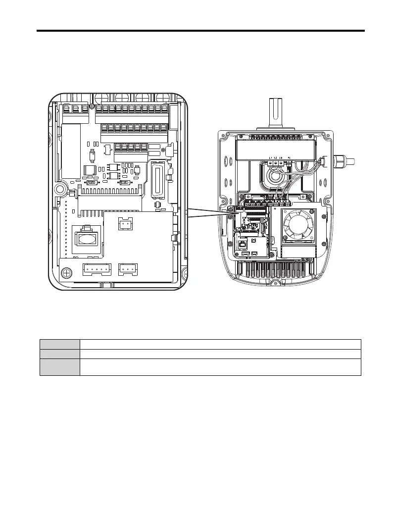
Control Circuit Terminals
The figure below shows the control circuit terminal arrangement. The drive is equipped with
screwless terminals.
Note:
Use a straight-edge screwdriver with a blade width of max 2.5 mm and a
thickness of max 0.6 mm to release the terminals.
There are three DIP switches, S1 to S3, located on the terminal board
SW1 Switches analog input A2 between voltage and current input
SW2 Enables or disables the internal RS422/485 comm. port terminal resistance.
SW3
Used to select sourcing (PNP)/sinking (NPN, default) mode for the digital inputs (PNP requires
external 24 Vdc power supply)
R+R-S+S-IG
+VACAMACMP P1P2PCA1A2
S6
SCHCH1H2RPMAMB
S1 S2
S3
MC S1S2S3S4S5
R+R-S+S-IG
+VACAMACMP P1P2PCA1A2
S6
SCHCH1H2RPMAMB
S1 S2
S3
MC S1S2S3S4S5
WWW.NNC.IR

 Loading...