

S
Sean BrownSep 23, 2025
What to do if YASKAWA DC Drives show ASIC version fault?
- AAnthony LopezSep 23, 2025
An ASIC version fault in YASKAWA DC Drives indicates a faulty Inverter control circuit, requiring replacement of the Inverter.
What to do if YASKAWA DC Drives show ASIC version fault?
An ASIC version fault in YASKAWA DC Drives indicates a faulty Inverter control circuit, requiring replacement of the Inverter.
Why am I getting a ground fault error on my YASKAWA DC Drives?
If a ground fault occurs in YASKAWA DC Drives, it's likely due to a ground fault at the Inverter output, which can be caused by motor burn damage, worn insulation, or a damaged cable. To fix this, reset the fault after correcting its cause.
What causes inverter overload on YASKAWA DC Drives?
An inverter overload in YASKAWA DC Drives can be caused by: * A load that is too heavy or acceleration/deceleration times that are too short. * Incorrect V/f characteristics voltage. * An Inverter capacity that is too low. Solutions include checking the load and acceleration/deceleration times, verifying the V/f characteristics, or replacing the Inverter with a larger capacity one.
How to fix motor overload on YASKAWA DC Drives?
Motor overload in YASKAWA DC Drives can occur if: * The load is too heavy, or the acceleration/deceleration/cycle times are too short. * The V/f characteristics voltage is too high or low. * The Motor Rated Current (E2-01) is set incorrectly. To resolve this, check the load and acceleration/deceleration times, verify the V/f characteristics, and ensure the Motor Rated Current Setting (E2-01) is correct.
What to do if YASKAWA Varispeed E7 show main circuit overvoltage?
Main circuit overvoltage in YASKAWA DC Drives can be caused by: * Deceleration time being too short, leading to excessive regenerative energy from the motor. * The power supply voltage being too high. To resolve this, increase the deceleration time, connect a braking option, or decrease the voltage to be within the inverter's specifications.
How to troubleshoot inrush current prevention circuit fault in YASKAWA DC Drives?
An inrush current prevention circuit fault in YASKAWA DC Drives may be due to: * A failed MC in the main circuit. * A burned-out MC excitation coil. To resolve this, try turning the power supply off and on. If the fault persists, replace the Inverter.
How to resolve cooling fin overheating in YASKAWA DC Drives?
Overheating of the cooling fin in YASKAWA DC Drives can occur if: * The ambient temperature is too high. * There is a nearby heat source. * The Inverter's cooling fan has stopped. To resolve this, install a cooling unit, remove any nearby heat sources, or replace the cooling fan.
What to do if YASKAWA Varispeed E7 have control power fault?
To address a control power fault in YASKAWA DC Drives, try turning the power supply off and on. If the fault continues, replace the Inverter.
What causes main circuit voltage fault in YASKAWA Varispeed E7 DC Drives?
A main circuit voltage fault in YASKAWA DC Drives can be caused by: * An open-phase in the input power supply. * A momentary power loss. * Loose wiring terminals for the input power supply. * Excessive voltage fluctuations in the input power supply. * Poor voltage balance between the phases. To fix this, reset the fault after correcting its cause.
What causes Digital Operator Communications Error 2 on YASKAWA Varispeed E7 DC Drives?
A Digital Operator Communications Error 2 in YASKAWA DC Drives can be caused by: * The Digital Operator not being connected properly. * Faulty Inverter control circuits. To resolve this, disconnect and reconnect the Digital Operator. If the problem continues, replace the Inverter.
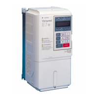
Provides an overview of the Varispeed E7 series, its applications, and models.
Details checks to perform immediately after receiving the inverter to ensure correct delivery.
Presents exterior diagrams and dimensions for various inverter models.
Outlines conditions for the installation site, including temperature, humidity, and environmental factors.
Specifies the required installation orientation and clearance for proper heat dissipation.
Provides instructions on how to remove and reattach the terminal cover for wiring.
Guides users on safely removing and attaching the digital operator and front cover.
Illustrates example connections between the inverter and typical peripheral devices.
Presents a detailed connection diagram for the inverter, showing all terminals and connections.
Shows the arrangement and identification of terminal blocks for control and main circuits.
Details wiring specifications for main circuit terminals, including wire sizes and connectors.
Provides guidance on wiring control circuit terminals and their specifications.
Lists essential checks to perform after all wiring has been completed to ensure correctness.
Describes the displays and functions of the digital operator interface.
Explains the different operating modes of the inverter and how to switch between them.
Outlines the step-by-step procedure for performing trial operation of the inverter.
Details the process of conducting the trial operation, including application confirmation and power on.
Provides advice on adjusting constants to resolve issues like hunting or vibration during trial operation.
Explains the structure and meaning of user constant tables and their components.
Shows the hierarchy of the digital operator display functions and access levels.
Lists all user constants that can be set in the inverter, organized by category.
Covers settings related to application requirements, such as carrier frequency selection.
Explains how to select the source for the frequency reference input.
Details the methods for selecting the source of the run command for inverter operation.
Describes various methods for stopping the inverter when a stop command is input.
Explains how to set acceleration and deceleration times and S-curve characteristics.
Details methods for adjusting frequency references using analog inputs and related constants.
Explains how to limit the maximum and minimum output frequencies.
Describes the types of frequency detection methods available for monitoring.
Covers functions like torque compensation and hunting prevention for better efficiency.
Details functions for preventing motor stalling, detecting torque, and motor overload.
Explains how the inverter can automatically restart after a momentary power loss or transient error.
Covers inverter overheat protection, input phase loss detection, and ground fault protection.
Explains the functions of various input terminals for controlling the inverter.
Describes the functions of the digital multifunction output terminals.
Details the constants used for monitoring analog and pulse outputs.
Covers functions like MEMOBUS communications and the timer function.
Explains the various functions and settings accessible via the Digital Operator.
Details alarm functions, fault detection, operation errors, and autotuning errors.
Provides guidance on identifying and resolving common issues like constant setting errors or motor operation problems.
Outlines the schedule and procedures for routine maintenance and inspection.
Defines the maintenance period and general guidelines for upkeep.
Lists key items to check during daily system operation.
Details items to check during periodic maintenance, emphasizing safety precautions.
Lists parts requiring maintenance based on their service life and usage conditions.
Provides instructions for replacing cooling fans in different inverter models.
Guides users on removing and mounting the control circuit terminal card.
Lists the standard technical specifications of the inverter.
Provides detailed specifications categorized by specific inverter models.
Offers precautions for selecting and installing the inverter.
Lists precautions to consider when using the inverter with standard or special motors.
Provides a reference list of user constants available in the inverter.