5-48
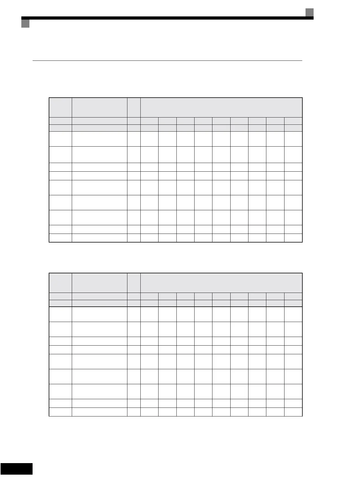
Factory Settings that Change with the Inverter Capacity (o2-04)
200 V Class Inverters
Note: Attach a Momentary Power Interruption Compensation Unit if compensation for power interruptions of up to 2.0 seconds is required for 200 V class
Inverters with outputs of 0.4 to 11 kW.
* If C6-02 is set to 0, 1, or F and the initial value of C6-03 and C6-04 is 2.0 kHz, the initial settings for C6-02 are as follows: 2: 5.0 kHz, 3: 8.0 kHz, 4: 10
kHz, 5: 12.5 kHz, and 6: 15 kHz. If the carrier frequency is set higher than the factory setting for Inverters with outputs of 30 kW or more, the Inverter
rated current will need to be reduced.
Con-
stant
Number
Name Unit Factory Setting
– Inverter Capacity kW 0.4 0.75 1.5 2.2 3.7 5.5 7.5 11 15
o2-04 kVA selection – 0 1 2 3 4 5 6 7 8
b8-04
Energy-saving coeffi-
cient
–
288.20 223.70 169.40 156.80 122.90 94.75 72.69 70.44 63.13
C6-02
Carrier frequency selec-
tion
*
–666666666
E2-01 Motor rated current A 1.90 3.30 6.20 8.50 14.00 19.60 26.60 39.7 53.0
E2-03 Motor no-load current A 1.20 1.80 2.80 3.00 4.50 5.10 8.00 11.2 15.2
E2-05
Motor line-to-line resis-
tance
Ω
9.842 5.156 1.997 1.601 0.771 0.399 0.288 0.230 0.138
L2-02
Momentary power loss
ridethru time
s 0.1 0.1 0.2 0.3 0.5 1.0 1.0 1.0 2.0
L2-03
Min. baseblock (BB)
time
s 0.1 0.2 0.3 0.4 0.5 0.6 0.7 0.8 0.9
L2-04 Voltage recovery time s 0.3 0.3 0.3 0.3 0.3 0.3 0.3 0.3 0.3
L8-02 Overheat pre-alarm level °C959595959595959595
Con-
stant
Number
Name Unit Factory Setting
– Inverter Capacity kW 18.5 22 30 37 45 55 75 90 110
o2-04 kVA selection – 9 A B C D E F 10 11
b8-04
Energy-saving coeffi-
cient
–
57.87 51.79 46.27 38.16 35.78 31.35 23.10 23.10 23.10
C6-02
Carrier frequency selec-
tion*
–664333331
E2-01 Motor rated current A
65.8 77.2 105.0 131.0 160.0 190.0 260.0 260.0 260.0
E2-03 Motor no-load current A
15.7 18.5 21.9 38.2 44.0 45.6 72.0 72.0 72.0
E2-05
Motor line-to-line resis-
tance
Ω
0.101 0.079 0.064 0.039 0.030 0.022 0.023 0.023 0.023
L2-02
Momentary power loss
ridethru time
s 2.0 2.0 2.0 2.0 2.0 2.0 2.0 2.0 2.0
L2-03
Min. baseblock (BB)
time
s 1.0 1.0 1.1 1.1 1.2 1.2 1.3 1.5 1.7
L2-04 Voltage recovery time s 0.6 0.6 0.6 0.6 0.6 1.0 1.0 1.0 1.0
L8-02 Overheat pre-alarm level °C959595959595959595
Artisan Technology Group - Quality Instrumentation ... Guaranteed | (888) 88-SOURCE | www.artisantg.com