Wiring Main Circuit Terminals
2-11
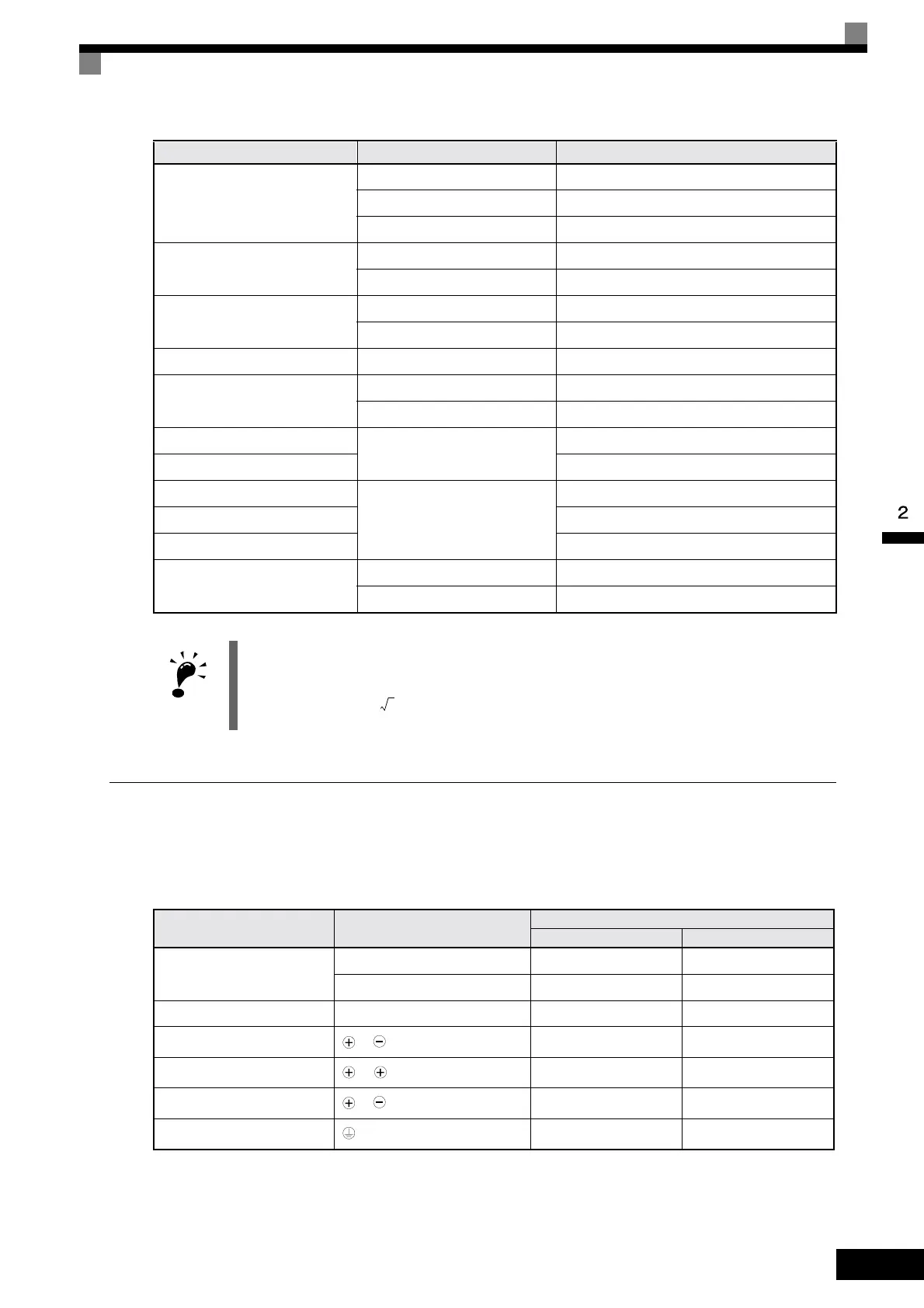
Main Circuit Terminal Functions
Main circuit terminal functions are summarized according to terminal symbols in Table 2.4. Wire the termi-
nals correctly for the desired purposes.
Table 2.4 Main Circuit Terminal Functions (200 V Class and 400 V Class)
8
M5 8 / 5
M6 8 / 6
M8 8 / 8
14
M6 14 / 6
M8 14 / 8
22
M6 22 / 6
M8 22 / 8
30/38 M8 38 / 8
50/60
M8 60 / 8
M10 60 / 10
80
M10
80 / 10
100 100 / 10
100
M12
100 / 12
150 150 / 12
200 200 / 12
325
M12 x 2 325 / 12
M16 325 / 16
IMPORTANT
Determine the wire size for the main circuit so that line voltage drop is within 2% of the rated voltage. Line
voltage drop is calculated as follows:
Line voltage drop (V) =
x wire resistance (W/km) x wire length (m) x current (A) x 10
-3
Purpose Terminal Symb ol
Model: CIMR-F7C
200 V Class 400 V Class
Main circuit power input
R/L1, S/L2, T/L3 20P4 to 2110 40P4 to 4300
R1/L11, S1/L21, T1/L31 2022 to 2110 4022 to 4300
Inverter outputs U/T1, V/T2, W/T3 20P4 to 2110 40P4 to 4300
DC bus terminals
1,
20P4 to 2110 40P4 to 4300
DC reactor connection
1, 2
20P4 to 2018 40P4 to 4018
Braking Unit connection
3,
2022 to 2110 4022 to 4300
Ground 20P4 to 2110 40P4 to 4300
Wire Thickness (mm
2
)
Terminal Screws Size
3
Artisan Technology Group - Quality Instrumentation ... Guaranteed | (888) 88-SOURCE | www.artisantg.com