3 Electrical Installation
EN 26 YASKAWA Europe TOEP C710606 101A - V1000 MMD IP65 Motor Mounted Drive - Quick Start Guide
Control Circuit
The control terminal board is equipped with screwless terminals. Always use wires within
the specification listed below. For safe wiring it is recommended to use solid wires or flexi-
ble wires with ferrules. The stripping length respectively ferrule length should be 8 mm.
Main and Control Circuit Wiring
Wiring the Main Circuit Input
Consider the following precautions for the main circuit input.
• Use fuses recommended in Main Circuit on page 25 only.
• When using residual current monitoring or detection devices (RCM/RCD), make sure the
devices are designed for use with AC drives (e.g. type B according to IEC 60755).
• If using a ground fault circuit breaker, make sure that it can detect both DC and high fre-
quency current.
• If using an input switch make sure that the switch does not operate more than once every
30 minutes.
• Use an AC reactor on the input side of the drive:
–To suppress harmonic current.
–To improve the power factor on the power supply side.
–When using an advancing capacitor switch.
–With a large capacity power supply transistor (over 600 kVA).
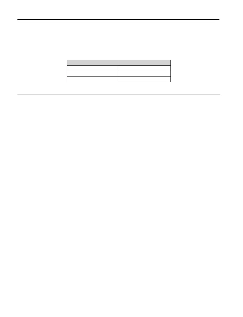
Wire Type Wire size (mm
2
)
Solid 0.2 to 1.5
Flexible 0.2 to 1.0
Flexible with ferrule 0.25 to 0.5
WWW.NNC.IR

 Loading...