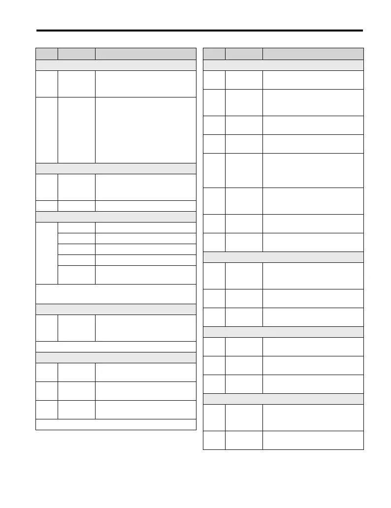
6 Parameter Table
YASKAWA Europe TOEP C710606 101A - V1000 MMD IP65 Motor Mounted Drive - Quick Start Guide EN 39
ENGLISH
Duty Mode and Carrier Frequency
C6-01
Normal/
Heavy Duty
Selection
0: Heavy Duty (HD)
1:Normal Duty (ND)
C6-02
Carrier
Frequency
Selection
1:2.0 kHz
2:5.0 kHz
3:8.0 kHz
4:10.0 kHz
5:12.5 kHz
6:15.0 kHz
7 to A: Swing PWM1 to 4
F: User defined
Frequency References
d1-01
to
d1-16
Frequency
Reference
1 to 16
Set the multi-speed references 1 to
16.
d1-17 Jog Speed Jog speed
V/f Pattern
E5-01
<1>
Motor Codes
Description
3 SPRiPM 8 poles
2 3000 rpm
3 1500 rpm
35 to
3F
400 V, 1.5 kW to 18.5 kW
<1> Refer to Motor Codes for E5-01 on page 35
for a complete overview of available motor codes.
Digital Input Settings
H1-01
to
H1-06
DI S1 to S6
Function
Selection
Selects the function of terminals S1
to S6.
Major functions are listed at the end of the table.
Digital Output Settings
H2-01
DO MA/MB
Function
Set the function for the relay output
MA-MB-MC.
H2-02
DO P1
Function
Sets the function for the photocou-
pler output P1.
H2-03
DO P2
Function
Sets the function for the photocou-
pler output P2.
Major functions are listed at the end of the table.
Par. Name Description
Analog Input Setting
H3-01
A1 Signal
Level Sel.
0:0 to +10 V (neg. input is zeroed)
1:0 to +10 V (bipolar input)
H3-02
A1
Function
Sel.
Assign a function to terminal A1.
H3-03 A1 Gain
Sets the input value in % at 10 V
analog input.
H3-04 A1 Bias
Sets the input value in % at 0 V
analog input.
H3-09
A2 Signal
Level
Selection
0:0 to +10 V (neg. input is zeroed)
1:0 to +10 V (bipolar input)
2:4 to 20 mA (9 bit input)
3:0 to 20 mA
H3-10
A2
Function
Sel.
Assign a function to terminal A2.
H3-11 A2 Gain
Sets the input value in % at
10 V/20 mA analog input.
H3-12 A2 Bias
Sets the input value in % at
0 V/0 mA/4 mA analog input.
Analog Input Setting
H4-01
AM
Monitor
Selection
Enter value equal to U1-
monitor values. Example: Enter
“103” for U1-03.
H4-02 AM Gain
Sets terminal AM output voltage
equal to 100% monitor value.
H4-03 AM Bias
Sets terminal AM output voltage
equal to 0% monitor value.
Pulse Input Setting (Free. ref. input)
H6-02
RP Input
Scaling
Sets the number of pulses (in Hz)
that is equal to 100% input value.
H6-03
Pulse Train
Input Gain
Sets the input value in % at pulse
input with H6-02 frequency.
H6-04
Pulse Train
Input Bias
Sets the input value in % at 0 Hz
pulse input frequency.
Pulse Output Setting
H6-06
MP Monitor
Sel.
Enter value equal to U-
monitor values. Example: Enter
“102” for U1-02.
H6-07
MP Monitor
Scaling
Sets the number of output pulses
when the monitor is 100% (in Hz).
Par. Name Description
WWW.NNC.IR

 Loading...