Date: 08/01/05, Rev: 05-08 Page 10 of 17 TM.F7SW.096
4.2 Monitors (U1-XX) (continued)
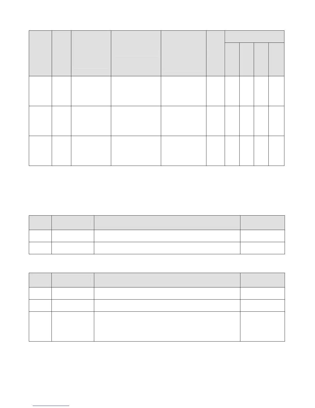
Control Mode *1
Monitor Number
Modbus Address
Monitor Name
Digital
Operator
Display
Description
Scaling for Multi-
function Analog
Outputs
Terminals
FM and AM
(H4-01, H4-04)
Unit
V/f
V/f w/ PG
Open Loop
Vector
Flux Vector
U1-94 724H
PID Integral
Output
PID I Output
Displays the PID
integral value as a
percentage of
maximum output
frequency.
100%:
Maximum Output
Frequency
(E1-04)
0.1%
*2
Q Q Q Q
U1-95 725H
PID Derivative
Output
PID D Output
Displays the PID
derivative value as
a percentage of the
maximum output
frequency.
100%:
Maximum Output
Frequency
(E1-04)
0.1%
*2
Q Q Q Q
U1-96 726H
PID Setpoint
PID Setpoint
Displays the PID
setpoint as a
percentage of the
maximum output
frequency.
100%:
Maximum Output
Frequency
(E1-04)
0.1%
*2
Q Q Q Q
*1: Access Level (A1-01): Q = “Quick Start”, A = “Advanced”, F = “Factory”.
*2: Unit and scaling based on O1-03 (Display Scaling) setting. When O1-03 ≥ 40 (custom units), the displayed
units on the keypad are determined by parameter P2-09.
*3: Unit and scaling based on P2-10 (Output Monitor Units) setting. Parameter P2-10 operates exactly the same
way as O1-03. When P2-10 ≥ 40 (custom units), the displayed units on the keypad are determined by
parameter P2-09.
4.3 Multi-function Digital Input Settings (H1-0X)
Setting Display Description
Available For All
Control Modes
80
Positive Integral
Hold
Closed: Integral is permitted to decrease, but not increase. √
81
Negative
Integral Hold
Closed: Integral is permitted to increase, but not decrease. √
√: Available.
4.4 Multi-function Digital Output Settings (H2-0X)
Setting Display Description
Available For All
Control Modes
40 Feedback High
Closed: PID feedback has exceeded P1-02 level for the time
set in P1-03.
√
41 Feedback Low
Closed: PID feedback has fallen below the P1-05 level for the
time set in P1-06.
√
42
Blowdown
Valve
Closed: Drive has received a run command, the P2-08 delay
timer has expired, and the PID feedback high detection
function is not on (level set in P1-02). Opens immediately
after the run command is removed or the PID feedback high
detection function is satisfied.
√
√: Available.
 Loading...


