12 YASKAWA ELECTRIC TOBP C730600 49A V1000 Option MECHATROLINK-II Installation Manual
4 MECHATROLINK-II Option Components
4 MECHATROLINK-II Option Components
◆ MECHATROLINK-II Option
Figure 1
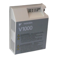
Figure 1 Option Unit
Note: For details on the LEDs, Refer to MECHATROLINK-II Option LED Display on page 14.
A – LED (RUN: green)
<1> Cables are not connected to the MECHATROLINK-II Option and are packaged separately in the box.
I – Connector
B – LED (ERR: red) J – MECHATROLINK-II PCB
C – LED (TX: green) K – Attachment screw hole for option cover
D – LED (RX:green) L – Nameplate
E – Attachment screw (M3) M – Function Earth cable connection (FE)
F – Option cover N – Ground Cable
<1>
G – Option connector O – Through-hole for cable
H – Mounting clip
SI-T3
FE
RUN
ERR
TX
RX
D
C
B
E
F
G
H
K
J
H
N
M
I
L
O
MECHATROLINK-II
with cover attached
MECHATROLINK-II
with cover removed
Underside
 Loading...