Do you have a question about the Yeswelder YWM-160 and is the answer not in the manual?
Protect eyes, face, and body from welding hazards like spatter and flash.
Precautions for hazardous materials and confined spaces.
Cylinder safety, fire hazards, and fire fighting equipment.
Warnings about chemicals known to cause cancer and reproductive harm.
Potential hazards of EMF fields for pacemakers and health.
Safety precautions specific to engine-powered welding equipment.
Dangers of electric shock from electrode and work circuits.
Risks of burns from arc rays and the need for eye/body protection.
Health risks from welding fumes and gases, ventilation requirements.
Risks of sparks and welding causing fire or explosion.
Precautions for handling and storing compressed gas cylinders.
Safety guidelines for installation and grounding.
Details on input power, output ratings, and machine parameters.
Guidelines for choosing a dry, clean, and well-ventilated installation site.
Restrictions on stacking and placement recommendations for stability.
Identification of included welder accessories with numbers and names.
Brief overview of critical safety warnings before operation.
Overview of welding processes supported by the machine.
Definitions of common welding abbreviations like GMAW, SMAW, GTAW.
Explanation of buttons and adjustments on the front panel.
Details on voltage, amp/WFS, process, and mode selection buttons.
Identification of rear panel ports for power, gas, and cables.
Description of the wire spool spindle, brake, and wire feeder.
Guidelines for secure placement and safe handling of gas cylinders.
Steps for connecting the regulator and setting gas flow rate.
Instructions for placing the wire spool on the spindle.
Step-by-step guide to threading wire into the MIG gun assembly.
Understanding machine specifications and duty cycle ratings.
Visual guide for correct and incorrect wire feeding setup.
Explanation of the thermal protection system and its reset behavior.
Steps for preparing the work area and the machine for welding.
Guidance on choosing the correct diameter for steel wire.
Table for selecting appropriate shielding gas based on metal type.
Connecting work clamp, selecting MIG/MAG process, and setting parameters.
How to use the Smart MIG pre-defined settings.
Table detailing Smart MIG settings for different materials and sizes.
How to adjust wire feed speed and voltage in manual mode.
Table for manual MIG settings based on material and size.
Connecting TIG torch, safety warnings, and gas usage.
Steps for initiating arc and welding with the TIG torch.
Best practices for TIG welding quality.
Guide to electrode polarity and recommended uses for different types.
Steps for striking an arc and maintaining it for stick welding.
Recommended current ranges for E6013 electrodes.
Basic steps for keeping the welder in good condition.
Tips for maintaining contact tips and gas nozzles.
Explanation of the three-step procedure for diagnosing issues.
Troubleshooting for circuit breaker trips and no output power.
Common problems and solutions for MIG welding.
Diagnosing issues when no arc or wire feed occurs.
Troubleshooting when the arc is present but wire is not feeding.
Solutions for welds with insufficient output or penetration.
Addressing issues where the wire burns back to the contact tip.
Causes and solutions for poor arc initiation in TIG welding.
Troubleshooting contaminants causing black areas in TIG welds.
Addressing issues causing an unstable arc in TIG welding.
Causes and solutions for an arc that wanders during TIG welding.
Problems preventing the Lift TIG arc from initiating.
Causes and solutions for rapid tungsten consumption.
Addressing tungsten contamination and its effects.
Causes and solutions for poor arc initiation in stick welding.
Troubleshooting electrodes that blast off or stick to the puddle.
Causes of small cavities or holes in weld metal.
Solutions for excessive scattering of molten metal particles.
Addressing failure of weld metal to fuse completely with base metal.
Solutions for shallow fusion between weld metal and base metal.
Causes and solutions for weld metal melting completely through base metal.
Schematic representation of the welder's internal electrical components.
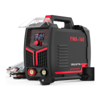
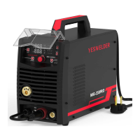
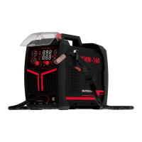
The YWM-160 is an IGBT Inverter Multi-Process Welder designed for a variety of welding tasks, including MIG, MAG, Flux-Cored, Stick, and Lift TIG welding. This versatile machine is built to make welding accessible and affordable, catering to both experienced welders and those new to the craft. Its compact and portable design allows for easy setup and use in various work environments, from workshops to outdoor job sites.
The YWM-160 offers multiple welding processes, making it a highly adaptable tool. For MIG (Metal Inert Gas) and MAG (Metal Active Gas) welding, it is capable of working with steel, mild steel, and stainless steel. This process is ideal for welding on thinner and cleaner materials where a very clean, aesthetically pleasing weld is desired, such as in automotive body panels. The machine supports both solid steel wire and stainless steel wire in diameters of .030" to .035" (0.8mm to 0.9mm). It requires a shielding gas to protect the weld until it cools, with appropriate gas selection based on the material being welded. The YWM-160 does not have a built-in gas solenoid, necessitating a one-piece gas valve TIG torch for gas control, which must be manually opened before and closed after welding.
For Flux-Cored Arc Welding (FCAW), the YWM-160 can be used without external shielding gas, as the flux within the wire provides the necessary protection. This makes it suitable for outdoor use or in situations where gas cylinders are impractical.
The machine also supports Shielded Metal Arc Welding (SMAW), commonly known as Stick welding. This process is versatile and effective for welding a wide range of materials and thicknesses, often used in construction and repair. The YWM-160 accommodates various electrode types, with recommendations for polarity and usage provided to achieve optimal results.
Additionally, the YWM-160 is capable of DC Lift TIG (Gas Tungsten Arc Welding). This process is known for producing high-quality, precise welds, especially on thin materials. It requires a TIG torch (not included) and a lanthanated tungsten electrode. The lift arc technique ensures a clean arc start by touching the tungsten electrode to the workpiece and then lifting it slightly to initiate the arc. Shielding gas, typically 100% Argon, is essential for TIG welding to protect the weld pool from atmospheric contamination.
The YWM-160 features a user-friendly control panel with clear displays for voltage and amperage/wire feed speed. It includes a Smart/Manual selection button, allowing users to choose between predefined settings for ease of use (Smart Mode) or fine-tune parameters manually. In Smart Mode, the machine preselects voltage and amperage based on the wire diameter and gas type, automatically adjusting the welding voltage for ideal arc conditions. Manual Mode provides greater control over wire feed speed and voltage. Process selection buttons allow toggling between MIG/MAG, Stick, and Lift TIG. Material and wire diameter selectors further simplify setup. Torch operation can be set to 2T (press and hold to weld, release to stop) or 4T (press and release to start, press and release again to stop), with 4T being particularly useful for long weld runs.
The YWM-160 is designed for straightforward installation and operation. Before use, it is crucial to read the entire manual and adhere to all safety precautions, including wearing appropriate personal protective equipment such as a welding helmet, flame-resistant clothing, gloves, and safety glasses. The machine should be placed in a dry, well-ventilated area to prevent overheating and dirt accumulation.
For MIG/MAG/Flux-Cored welding, the work clamp connection varies based on the process: positive for Flux-Cored and negative for MIG/MAG. The wire spool spindle accommodates 4-inch or 8-inch diameter spools, with an adjustable brake to prevent over-rotation. Feeding the welding wire through the gun assembly involves careful steps, including cutting the wire end straight, releasing the drive roller pressure arm, inserting the wire, and then adjusting the pressure to prevent slipping or crushing the wire. The contact tip and nozzle must be correctly installed and maintained for optimal performance. Gas cylinder connection involves securing the cylinder, attaching the regulator, and setting the gas flow rate.
For Stick welding, the electrode holder and work clamp are connected according to the recommended polarity for the specific electrode type. The amperage is set, and the arc is initiated by striking the electrode against the workpiece. Maintaining a steady travel speed and proper arc length are key to achieving quality welds.
For Lift TIG welding, the TIG torch cable connects to the negative socket, and the work cable to the positive socket. The tungsten electrode must be sharpened and set to the correct stick-out length. Shielding gas flow (Argon) is crucial and must be set to the appropriate rate. The lift arc technique allows for a controlled arc start, minimizing contamination.
The machine’s performance data plate provides essential information, including duty cycle ratings, which indicate the maximum welding time allowed within a 10-minute cycle before the machine requires cooling. An internal thermal protection system will engage if the duty cycle is exceeded, temporarily shutting off output to prevent damage.
Regular maintenance is vital for the longevity and optimal performance of the YWM-160. Key maintenance tasks include keeping the cabinet cover closed when not in use and ensuring all consumables—contact tips, nozzles, and liners—are clean and replaced as needed. Damaged or worn input power cables, ground cables, work clamps, or gun assemblies should be replaced promptly.
It is important to prevent grinding particles from entering the welder, as these conductive particles can accumulate and cause severe damage. Periodic cleaning of the welder, typically every six months or as needed, involves removing side panels and using compressed air to blow out accumulated dust and dirt. The wire liner should also be cleaned periodically, especially when changing wire spools.
The wire feed drive roller is subject to wear and should be replaced if it becomes worn or if it no longer makes proper contact with the welding wire. All cables should be checked periodically for good condition and absence of cracks.
For consumable-specific maintenance, the contact tip's purpose is to transfer welding current smoothly. If wire burns back into the tip or if the hole becomes worn, the contact tip must be cleaned or replaced. A worn-out contact tip can lead to unstable arc characteristics and difficult arc starting.
The gas nozzle must be kept clean to prevent spatter and slag buildup, which can cause erratic welds, reduced penetration, and overheating of the welding gun. If the nozzle becomes shorted due to buildup, it should be cleaned or replaced.
Before performing any maintenance, especially when removing side panels, it is critical to turn off the power switch and unplug the welder from the AC power source. Waiting several minutes for electrical energy to discharge is also recommended to reduce the risk of electric shock.
The troubleshooting guide in the manual helps users identify and resolve common issues by providing possible causes and recommended courses of action. If problems persist or if the user is unsure how to safely perform a repair, contacting customer support is advised.
| Output Current | 10-160A |
|---|---|
| Duty Cycle | 60% at 160A |
| Protection Class | IP21S |
| Input Voltage | 110V/220V |
| Welding Process | MMA (Manual Metal Arc) / Stick |
| Weight | 5.5 kg |
| Electrode Diameter Range | 1.6mm - 4.0mm |