EasyManua.ls Logo

YOKOGAWA Daqstation DX2000 User Manual

YOKOGAWA Daqstation DX2000
366 pages
To Next Page IconTo Next Page
To Previous Page IconTo Previous Page
Page #289 background imageLoading...
Page #289 background image
9-21
IM 04L42B01-01E
Computation and Report Functions (/M1 and /PM1 Options)
1
2
3
4
5
6
7
8
9
10
11
12
13
App
Index
• Parameters
Parameter Format Range Description
Report kind Hour Hourly report
Day Daily report
Week Weekly report
Month Monthly report
Report channel number Rxx
(xx are numerals)
R01 to R60
(varies by model)
DX report channel
Start date or time xx
(xx are numerals)
00 to 23 Specifies the start time
01 to 31 Specifies the start date
End date or time xx
(xx are numerals)
00 to 23 Specifies the end time
01 to 31 Specifies the end date
StartingandEndingDatesandTimes
Use the start date and time and end date and time to specify the parts of the report
file’s report data that you will output to the file that you create with the template. You can
specify the starting and ending dates (for daily reports) or times (for hourly reports).
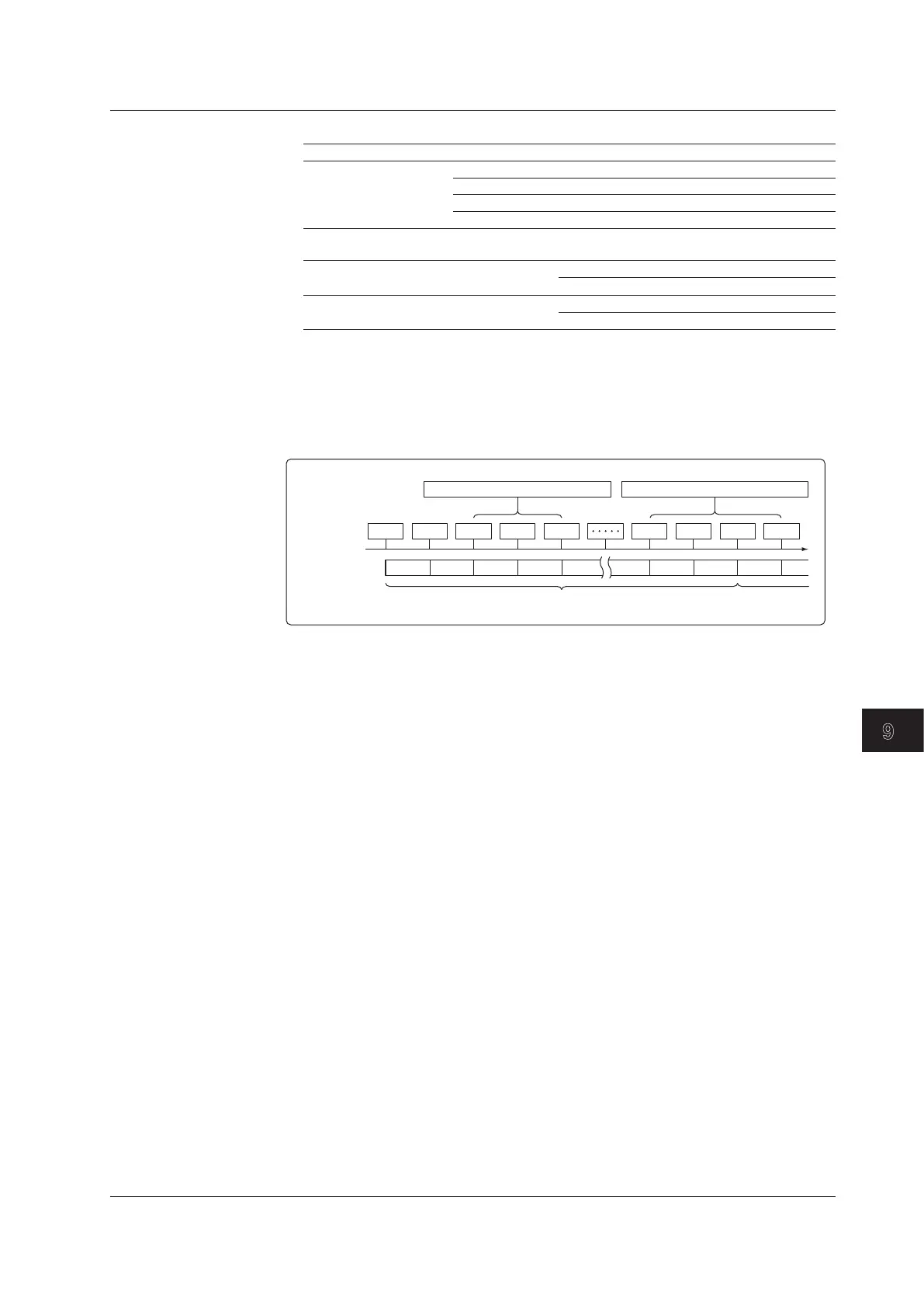
Example when the report type is hourly and the report was created at 18:00.
18:00 19:00
Report file 1
Report file 2
Report
creation time
$ReportDataSum(Hour,R01,20,22)$
$ReportDataSum(Hour,R01,16,19)$
20:00 21:00 22:00 16:00 17:00 18:00 19:00
Keyword:$ReportDataSum(Hour,R01,20,22)$
From the hourly data from 19:00:01 to 22:00:00, the report data (sums) of report
channel R01 for 20:00, 21:00, and 22:00 is output.
Keyword:$ReportDataSum(Hour,R01,16,19)$
From the hourly data from 15:00:01 to 19:00:00, the report data (sums) of report
channel R01 for 16:00, 17:00, and 18:00 is output. Because the report data for
19:00 is in another report file, it is not output.
Keyword:$ReportDataSum(Hour,R01)$
One file’s worth (18:00:01 to 18:00:00) of data from report channel R01 is output,
starting from 19:00.
When you omit the start and end times for an hourly report, the data for the hour
after the report creation time until the 24th hour is output. For daily reports, the data
for the day after the report creation time until the end of the month is output.
Keyword:$ReportDataSum(Hour,R01,08)$
From the hourly data from 07:00:01 to 18:00:00, the report data (sums) of report
channel R01 for 08:00 to 18:00 is output.
9.6CreatingaReportTemplate(Releasenumbers4andlater)

Table of Contents

Question and Answer IconNeed help?

Do you have a question about the YOKOGAWA Daqstation DX2000 and is the answer not in the manual?

YOKOGAWA Daqstation DX2000 Specifications

General IconGeneral
CategoryRecording Equipment
Operating Temperature0 to 50 °C (32 to 122 °F)
ModelDX2000
TypeData Acquisition Recorder
Input TypesThermocouple, RTD
Sampling RateUp to 100 ms per channel
Recording Interval100 ms to 60 min
DisplayColor LCD
Data StorageInternal memory
Communication InterfacesEthernet, USB
Power Supply100-240 VAC, 50/60 Hz

Summary

Chapter 1 Overview of Functions

1.1 Input Section

Describes input types, measurement channels, scan intervals, and A/D converter integration.

1.2 Alarms

Explains alarm types, hysteresis, delay, rate-of-change, and difference alarms.

1.3 Display

Details common display items, screen configuration, group display, and alarm indication.

1.4 Data Storage Function

Explains types of data the DX can record and how to store them.

1.6 Event Action and Remote Control Functions (/R1 and /PM1 Options)

Explains how specified actions are carried out when events occur.

1.7 Security Function

Details the DX security functions, including key lock and login.

1.8 Computation and Report Function (/M1 and /PM1 Options)

Explains defining equations in computation channels and creating reports.

Chapter 3 Measurement Channels and Alarms

3.1 Setting the Scan Interval and the Integration Time of the A/D Converter

Sets scan interval and A/D converter integration time.

3.3 Setting the Input Range

Sets the input range for each channel and defines input types.

3.5 Setting the Auxiliary Alarm Function

Configures alarm display and output relay operations.

3.7 Setting Alarms on Channels

Configures alarm types, values, and delay times for channels.

3.9 Performing Calibration Correction (/CC1 Option)

Corrects input values using segments for improved accuracy.

Chapter 4 Switching Operation Screens

4.2 Displaying the Measured Data as Waveforms, Values, or Bar Graphs

Details using trend, digital, and bar graph displays.

4.3 Displaying Past Measured Data (Historical Trend Display)

Explains methods to display past measured data.

Chapter 5 Operations for Changing the Displayed Contents

Chapter 6 Saving and Loading Data

6.1 Setting the Recording Conditions of the Measured Data

Sets methods for recording measured data.

6.2 Setting the Method for Saving the Data

Sets the method for recording measured data to the storage medium.

6.7 Managing the Files on the Storage Medium

Displays files, checks free space, deletes files, and formats media.

6.8 Loading and Displaying the Measured Data in the Storage Medium

Loads display or event data files from storage and displays waveforms.

6.9 Saving/Loading the Setup Data

Saves setup data to external media or loads from it.

Chapter 7 Customizing Actions Using the Event Action and Remote Control Functions (/R1 and /PM1 Options)

Chapter 8 Using the Security Function

8.1 Disabling the Key Operation (Key Lock Function)

Disables key operations by setting a password.

Chapter 9 Computation and Report Functions (/M1 and /PM1 Options)

9.1 Setting the Expression, Measurement Range, Alarm, Tag, and Data Storage on Computation Channels

Configures computation channel expressions, ranges, alarms, tags, and data storage.

9.2 Writing Expressions

Explains the meaning and syntax for writing expressions.

9.4 Starting/Stopping Computation, Resetting Computation, and Releasing Computation Data Dropout Display

Manages computation processes, including starting, stopping, and resetting.

9.5 Creating Reports

Sets up how hourly, daily, weekly, and monthly reports are created.

Chapter 10 Using External Input Channels (/MC1 Option)

10.1 Setting External Input Channels

Configures external input channels using Modbus client or master functions.

Chapter 11 Troubleshooting

11.1 A List of Messages

Provides a list of error codes, messages, and their explanations/countermeasures.

11.2 Troubleshooting

Offers troubleshooting steps for common operational issues.

Chapter 12 Calibration

12.2 Calibrating the DX

Recommends annual calibration for measurement accuracy.

Chapter 13 Specifications

13.1 Signal Input and Alarm

Lists specifications for signal input types and alarm functions.

13.3 Data Saving Function

Explains specifications for saving various data types.

Related product manuals