12-3
IM 04L42B01-01E
Calibration
12
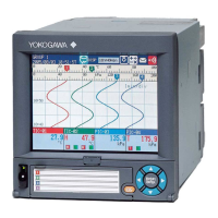
TemperatureMeasurementWhenUsinganRTD(ExamplefortheDX2010)
Decade resistance box
The resistance of three lead
wires must be equal.
(Model 2793-01 from Yokogawa
Meters & Instruments Corporation)
b
B
Input terminal
A
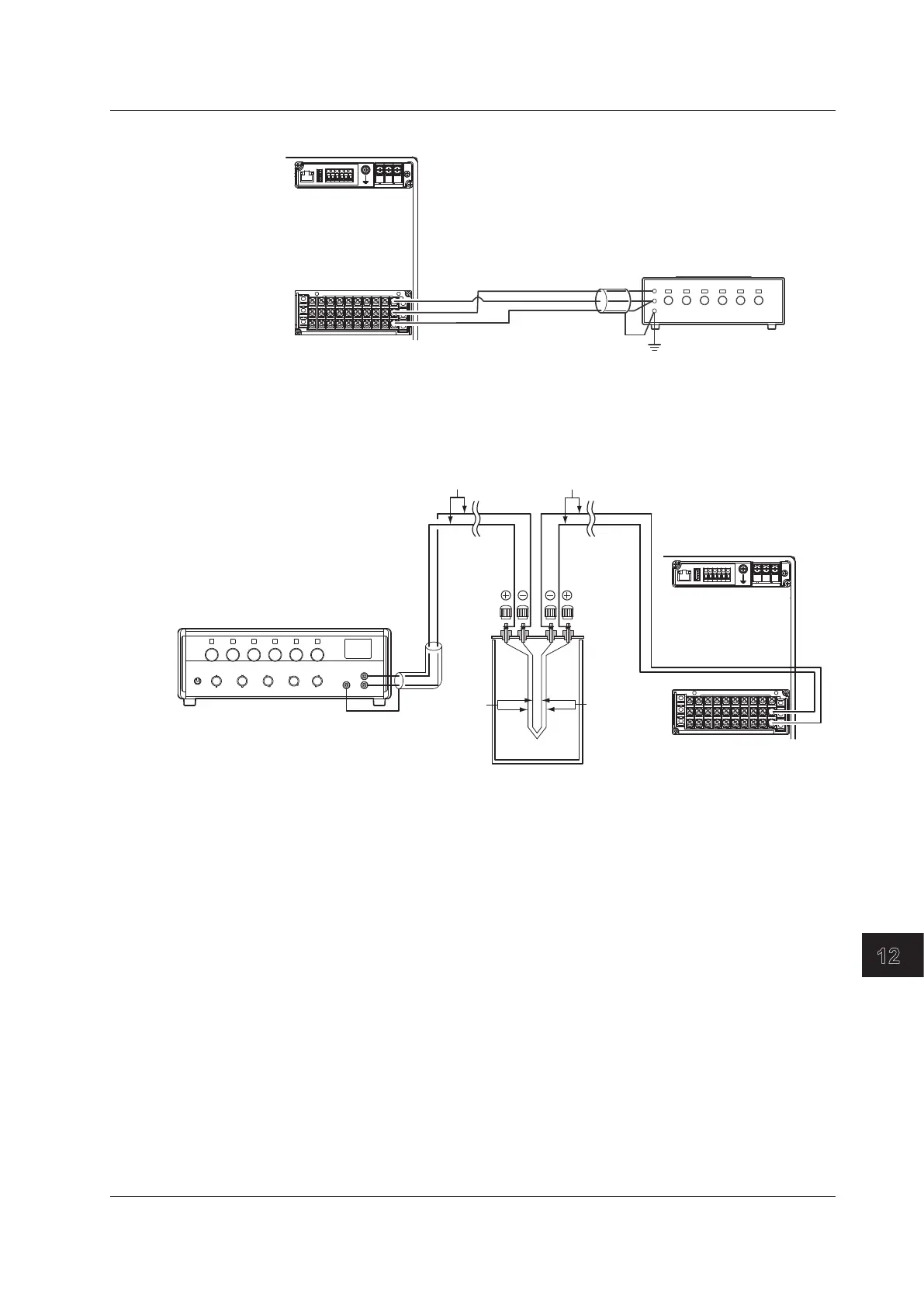
TemperatureMeasurementWhenUsingaThermocouple(Exampleforthe
DX2010)
Input terminal
extension wires
Thermocouple
wires
Copper
wires
Copper wires
DC voltage standard
–
+
+
–
°
C standard temperature device ZC-114/ZA-10 by Coper Electronics)
RJCofTCInput
As the measurement terminal of the DX is generally at room temperature, the actual
output of the thermocouple is different from the values given on the thermoelectromotive
force table based on 0°C. The DX performs compensation by measuring the temperature
at the input terminal and adding the corresponding thermoelectromotive force to the
actual output of the thermocouple. Therefore, when the measurement terminal is shorted
(equivalent to the case when the detector tip is 0°C), the measured value indicates the
temperature of the input terminal.
When calibrating the DX, this compensation voltage (thermoelectromotive force of 0°C
reference corresponding to the input terminal temperature) must be subtracted from the
output of the standard generator before application. As shown in the figure, by using the
0°Cstandardtemperaturedevicetocompensatethereferencejunctionat0°C,youcan
input the thermoelectromotive force of 0°C reference from the DC voltage standard and
perform the calibration.
12.2CalibratingtheDX

 Loading...