—Trigger function example—
•A to B(n) trigger
Example: Trigger on the 7th edge of signal on B. This is effective for
measurements with shifted timing, such as non-standard
video signal vertical/horizontal periods or motor reference
position pulses and drive pulses.
Input signal A
Input signal B
Trigger
•Serial pattern trigger (user dened)
Example: Trigger on an arbitrarily set pattern of up to 128 bits. This
is effective for detecting ID/Data and other portions of
proprietary communication formats.
Pattern conguration screen
Trigger
(Arbitrary pattern)
•Dual bus trigger
Example: Trigger on a combination of CAN and LIN bus triggers. I
2
C +
SPI bus triggers, and other combinations are possible.
Trigger when either LIN or CAN bus signal conditions become true
Input signal A CAN
Input signal B LIN
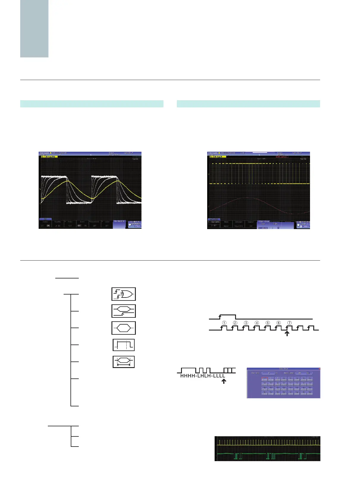
Real time lter with optimum noise reduction supports a wide range of frequencies (from 8 kHz to 200 MHz)
The DLM2000 series has two types of lters, one processed at the input circuit and one based on MATH functions. These lters are effective
for rejecting unwanted signals, allowing observation of only the desired bandwidths.
Trigger Function capturing combined analog/digital complex waveforms
The DLM2000 series comes with a variety of easy-to-congure triggers combining analog and logic inputs such as edge, enhanced, and B triggers.
Real time lters
Each channel has 14 low pass lters available from 8 kHz to
200 MHz. Waveforms of limited bandwidths are stored in internal
memory.
Cutoff frequencies: 200 MHz, 100 MHz, 20 MHz, 10 MHz, 5 MHz,
2 MHz, 1 MHz, 500 kHz, 250 kHz, 125 kHz,
62.5 kHz, 32 kHz, 16 kHz, and 8 kHz
Processing with built-in lters Filtering of a PWM waveform using computation
Input signal
Computed
waveform
Computed digital lters
The input waveform can be ltered using an IIR lter, which is a
MATH function. Filtered waveforms can be displayed at the same
time as the input waveform for comparison. You can select low
pass or high pass lters.
Cutoff frequency setting range: 0.01 Hz to 500 MHz
Edge trigger Edge
Enhanced triggers
Edge OR
B triggers
A Delay B
A to B(n)
Dual bus
(combination trigger of 2 serial busses)
Edge
(qualied)
State
Pulse width
State width
Serial (optional)
FlexRay/CAN/CAN FD/LIN/
SENT/PSI5/UART/I
2
C/SPI
(standard) user-dened
TV NTSC/PAL/SDTV/
HDTV/user dened
unctionality
Large selection of triggers and lters
F

 Loading...


