<2. Handling Cautions>
9
IM 01C25A01-01E
Model: EJX Series Date: October 22, 2003
Rev.3: July 16, 2019 Doc. No.: IFM022-A12 P.2
Yokogawa Electric Corpor ation
Specific conditions of use:
- Precautions sh all be taken to minimize the risk from electrostatic discharge of
painted parts.
- When the enc losure of the Pressure Transmitters is m ade of aluminum alloy, if it is
mounted in Zone 0, it m ust be install ed such that, even in the event of rare
incidents, an ignition source due to impac t and/o r fricti on spark s is excluded.
Entity Parameters [Groups: A, B , C, D, E, F and G]
Vmax: 30 V
Imax: 200 m A
Pmax: 1 W
Ci: 6 nF
Li: 0 µH
Entity Parameters [Groups: C, D, E, F and G]
Vmax: 30 V
Imax: 225 mA
Pmax: 1 W
Ci: 6 nF
Li: 0 µH
Notes:
1. Installation mu st be in ac cordance with the National Electric Code (NFPA70),
ANSI/ISA-RP12.06.01, and relevant local codes.
2. The Associated Apparatus must be FM -approved.
3. The f ollowing conditions must be satisfied.
Vmax
max
max
4. In case Nonincendive Field Wiring Concept is used f or the interconnecti on,
FM-appr oved Associated Noni ncendive Field Wiring Apparatus, which meets the
abov e conditions, must be used as the General Purpose Equipment.
5. The General Purpose Equi pment connected to the Associated Apparatus m ust not
use or generate a voltage more than Um of the Associated Apparatus.
6. The c ontrol drawing of the Associ ated Apparatus must be followe d whe n instal ling
the equipment.
7. Dust- tight condu it seals mu st be used when installed i n Class II or Clas s III
environments.
8. WARNIN G –ELECTROSTATIC CHARGE MAY CAUSE A N EXPLOSION HAZARD.
AVOID ANY ACTIONS THAT CAUS E THE GENERATIO N OF ELECTROSTATIC
CHARGE, SUCH AS RUB BING WITH A DRY CLOTH ON COATING FACE OF THE
PRODUCT.
9. WARNIN G – SUBSTITUTION OF COMPONENTS MAY IMPAIR INTRINSIC
SAFETY AND SUITABIL ITY FOR HAZARDOUS LOCATION
b. FM Intrinsically Safe/Nonincendive for
Fieldbus Type (Except for EJX9 0A)
locations.
FM 3611
Model: EJX-F Series Date: January 27, 2005
Rev.1: July 16, 2019 Doc. No.: IFM024-A12 P.1
Yokogawa Electric Corpor ation
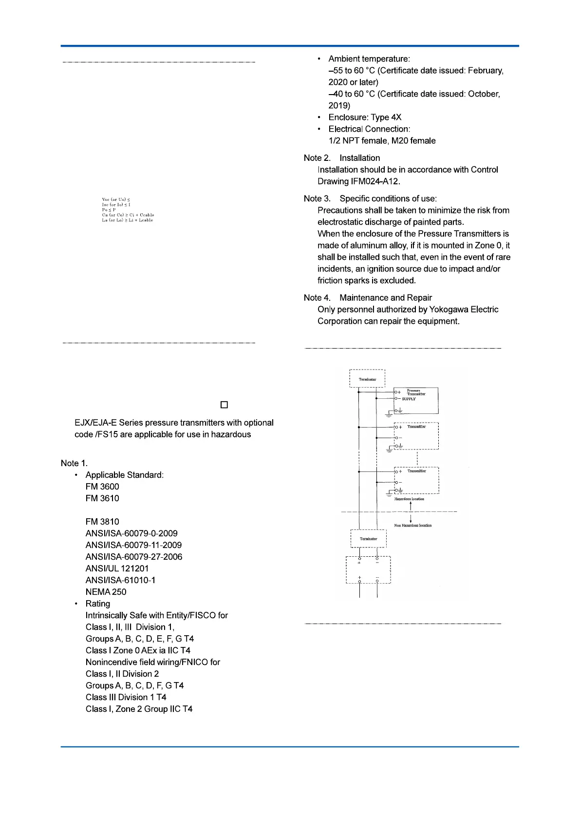
IFM 024
Control drawing (intrinsic safety)
A
(Safety Barrier)
Class I, II, III, Di v i s ion 1
Group s A, B, C, D , E, F , G
Class I, Zo n e 0 , Gr o up IIC

 Loading...