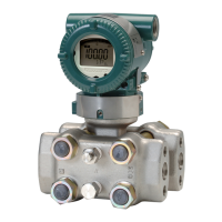
Do you have a question about the YOKOGAWA DPharp EJX***A Series and is the answer not in the manual?
Provides safety instructions for installation, wiring, operation, maintenance, and modification of the instrument.
Explains how to use DTMs with FieldMate for parameter configuration, including device files.
Covers fundamental setup parameters like Tag and Device Information, and Unit configuration.
Explains how to set the upper (URV) and lower (LRV) range values for pressure measurement.
Explains the sensor trim procedure for adjusting transmitter output to local conditions.
Describes how to set and configure alarms based on input pressure, static pressure, or temperature.
Explains how to perform self-diagnostics using HART configuration tools and interpret results.
Guides on using Self test and Status commands for diagnosing transmitter issues.
Covers advanced diagnostic functions like Multi-sensing Process Monitoring and Impulse Line Blockage Detection.
Explains how ILBD detects blockages using statistical analysis of process fluctuations.
Details limit parameters used to diagnose impulse lines as blocked based on pressure fluctuation.
Explains the Diag Mode (Stop, Calculation, Reference) for controlling ILBD operation.
Outlines the step-by-step flow for performing ILBD operation, including initial settings and checks.
Details how to set alarms and alerts for blockage detection and heat trace monitoring.
Explains how to check pressure stability and fluctuation values for proper ILBD operation.
Details the procedure to obtain reference values for pressure fluctuation under normal conditions.
Explains how to test blockage detection capability using simulated conditions.
Describes how to tune ILBD parameters to improve accuracy by adjusting threshold values or sampling period.
Explains how the transmitter calculates flange temperature and detects heat trace issues.
Lists common alarm messages, their causes, output operations, and countermeasures.
Lists error messages from the HART configuration tool, their causes, and countermeasures.
Covers safety accuracy, diagnostic response time, setup, and required parameters for SIS.
Explains the objective of proof testing to detect undetected failures in safety functions.
Covers checking alarm status in Diag Error and recording ILBD parameters like Diag Period and Lim values.
Details steps for simulating H Side Blocking, including valve closure and parameter recording.
Details steps for simulating L Side Blocking, including valve closure and parameter recording.
Details steps for simulating Both Side Blocking, including valve closure and parameter recording.
| Brand | YOKOGAWA |
|---|---|
| Model | DPharp EJX***A Series |
| Category | Transmitter |
| Language | English |


