<3. Parameter Setting>
3-19
IM 01C25T01-06EN
(1) Zero Trim
a. Zeroing—Pres Zero trim
Pres Zero trim carries out the zero adjustment and
automatically sets the applied “0” input values to the
output value of “0”, keeping the span constant. Use
this setting when the LRV is known to be 0 mmH
2
O.
• Procedure to call up the display
DD and DTM
(excluding EJX_
HART 5[1.2])
[Root Menu] → Diag/Service
→ Calibration → Pres Sensor
trim →
EJX_HART 5[1.2]
DTM
Calibration →
→ Pres Zero trim Adjust the lower point
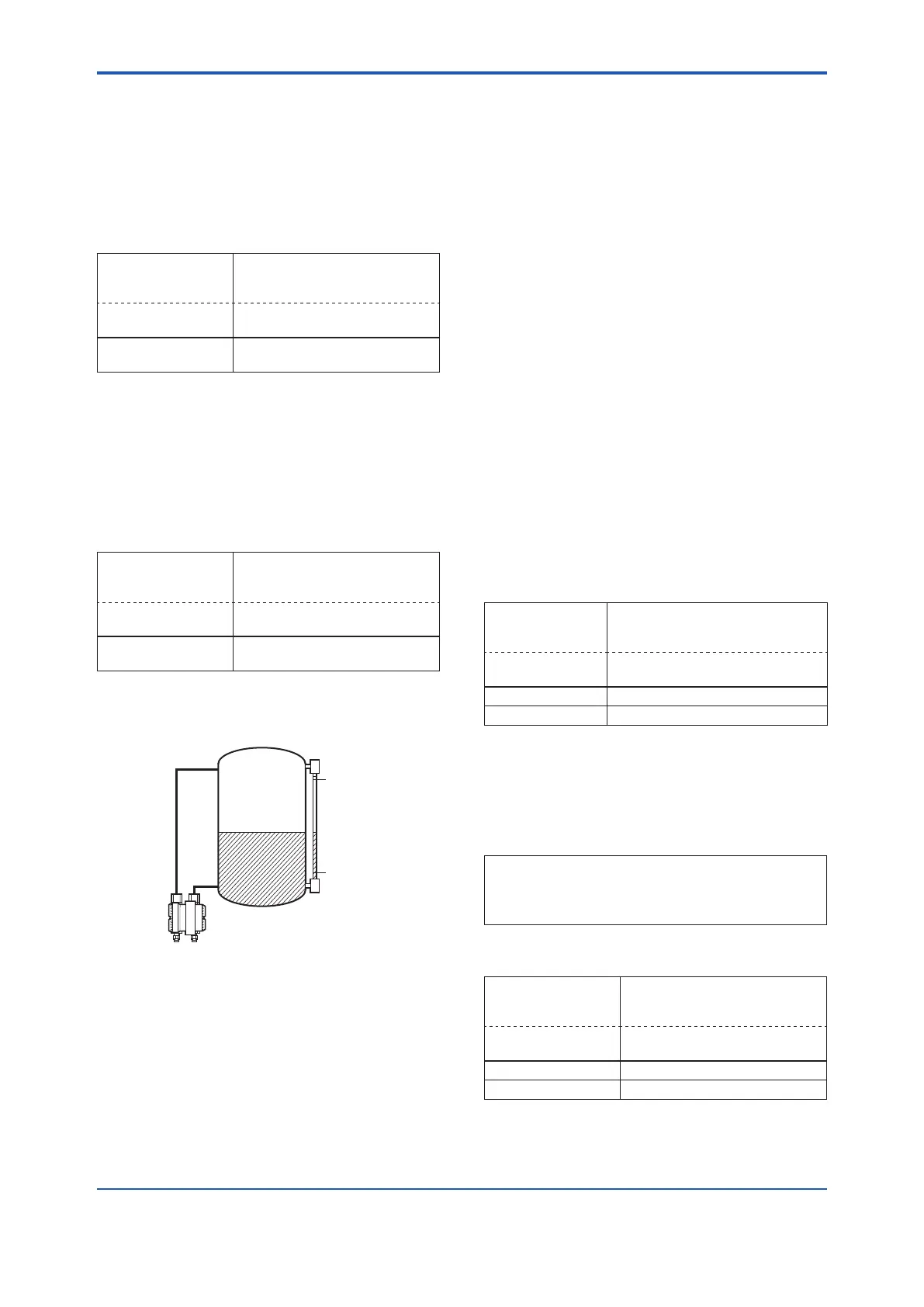
b. Level Adjustment—Auto, lower Pt
This zero adjustment calibrates the transmitter
output corresponding to the actual tank level. To
perform this adjustment, rst use a glass gauge
or the like to determine the actual tank level, then
enter the correct data as shown below.
• Procedure to call up the display
DD and DTM
(excluding EJX_
HART 5[1.2])
[Root Menu] → Diag/Service →
Calibration → Pres Sensor trim
→ Pres trim →
EJX_HART 5[1.2]
DTM
Calibration → Pres trim →
→ Auto, Lower Pt Auto trim for 0% point
F0306.ai
25.00 kPa
0.00 kPa
Actual level
13.50 kPa
DPharp span: 0 to 25.00 kPa
Actual level: 13.50 kPa
Transmitter output: 13.83 kPa
DPharp
c. Using External Zero-adjustment Screw
This method permits zero adjustment without
the HART conguration tool. Use a slotted
screwdriver to turn the zero-adjustment screw.
See the hardware manual for details.
Note that the parameter of Ext SW must be
“Enabled” to perform this adjustment. See
section 3.3.8 for the setting procedure.
(2) FullSensorTrim—AutoTrimandManual
Trim
Full sensor trim is carried out by performing Auto,
Lower Pt followed by Auto, Upper Pt.
Also, you can manually perform the trimming
procedure with Manual, Lower Pt and Manual,
Upper Pt.
The full sensor trim is a two-point adjustment,
and the lower point adjustment should always be
performed before the upper point adjustment in
order to maintain the pitch between the zero and
100% points within the calibration range.
In the manual method, the reference pressure
should also be applied to the transmitter at both
the lower and upper points. Without the reference
pressure, Manual, Lower Pt and Manual, Upper
Pt may not represent the correct value for each
adjustment point.
a. Auto Sensor Trim
Applying reference pressure of 0% and 100% of the
measurement range to the transmitter, adjust the
lower and upper points automatically.
• Procedure to call up the display
DD and DTM
(excluding EJX_
HART 5[1.2])
[Root Menu] → Diag/Service →
Calibration → Pres sensor trim →
Pres trim →
EJX_HART 5[1.2]
DTM
Calibration → Pres trim →
→ Auto, Lower Pt Auto trim for 0% point
→ Auto, Upper Pt Auto trim for 100% point
b. Manual Sensor Trim
Using the example below, follow the steps to
perform the full sensor trim by manually. The Pres
LTD (Manual, Lower Pt) and Pres UTD (Manual,
Upper Pt) represent the previously adjusted values.
Example: For the range of 1000 to 3000 mmH
2
O
Pres LTD (Manual, Lower Pt) = −4.0 mmH
2
O
Pres UTD (Manual, Upper Pt) = −3.0 mmH
2
O
<1> Call up the Manual, Lower Pt.
• Procedure to call up the display
DD and DTM
(excluding EJX_
HART 5[1.2])
[Root Menu] → Diag/Service →
Calibration → Pres sensor trim
→ Pres trim →
EJX_HART 5[1.2]
DTM
Calibration → Pres trim →
→ Manual, Lower Pt Manual trim for 0% point
→ Manual, Upper Pt Manual trim for 100% point

 Loading...


