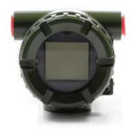
Do you have a question about the YOKOGAWA YTA610 and is the answer not in the manual?
Manual usage guidelines and importance of identification tag.
Safety instructions for handling and modifications, especially explosionproof types.
Precautions for installation, wiring, maintenance, modification, and disposal.
Explanation of safety symbols like WARNING, CAUTION, IMPORTANT, and NOTE.
Warranty period, inquiry process, and conditions not eligible for repair.
Information on HART trademark and other registered trademarks.
Availability of ATEX Ex related instruction manuals in different languages.
Explanation of hazardous substance control based on Chinese RoHS.
Location and verification of model and configuration on the nameplate.
Precautions for preventing damage during transit.
Storage conditions and recommendations for extended periods.
Recommendations for installation location based on ambient temperature and environmental requirements.
Caution regarding transceiver use near the installation area due to potential noise issues.
Precautions and procedures for insulation resistance and withstand voltage electrical tests.
Further requirements and differences for explosionproof type transmitters.
Technical data and conditions for ATEX intrinsically safe and fieldbus approvals.
Type of electrical connection based on marking near the port.
Technical data for FM (US) intrinsically safe and non-incendive approvals.
Technical data for CSA intrinsically safe and explosionproof approvals.
Control drawings for ATEX and IECEx Ex ia intrinsic safety installations.
Standards related to Electromagnetic Compatibility (EMC) and immunity influence.
Standards related to safety requirements, installation site, and pollution degree.
Identification and illustration of the transmitter's main components.
Explanation of slide switches for hardware error burnout direction and write protection.
Description of integral indicator display functions when powering on, including HART and BRAIN protocols.
Instructions and warnings for using local parameter setting via the integral indicator push buttons.
Overview of parameter configuration using the integral indicator's 3 push buttons.
Procedures for mounting the transmitter on a horizontal pipe using brackets.
Procedures for mounting the transmitter on a vertical pipe using brackets.
Note regarding user-supplied bolts for wall mounting.
Important precautions for wiring, including waterproofing, noise prevention, and conduit usage.
Description of the two-wire loop construction and connection requirements.
Guidelines for selecting input signal and output signal cables.
Procedures for connecting input and output signal cables to the terminals.
Cautions for general-use type wiring, including conduit usage and waterproofing sealant.
Importance and requirements for grounding the transmitter for proper operation.
Overview of instrument components and maintenance procedures.
Recommended equipment and procedures for verifying calibration.
List of equipment required for calibration, emphasizing traceable standards.
Step-by-step procedure for calibration to evaluate uncertainty.
Procedures for disassembling and assembling components for maintenance and part replacement.
Detailed steps for removing and installing the integral indicator assembly.
Flowcharts and guidelines for troubleshooting abnormal measured values and instrument issues.
Basic flowchart to identify the cause of abnormal process measurements.
Example troubleshooting flow illustrating common operational issues.
List of error codes displayed on the integral indicator for HART and BRAIN protocols.
Detailed standard specifications for the YTA710 model, including performance and functional aspects.
Performance and functional specifications for the YTA610 model.
Standards related to safety requirements, installation site, and pollution degree.
Compliance with EU RoHS directive and production site information.
Enclosure material, degrees of protection, mounting, terminal screws, indicator, and weight.
Explanation of model codes, suffix codes, and their corresponding descriptions.
Details of optional specifications available for the YTA series transmitters.
Dimensional drawings and specifications for horizontal, vertical pipe mounting, and terminals.
| Brand | YOKOGAWA |
|---|---|
| Model | YTA610 |
| Category | Transmitter |
| Language | English |


