EasyManua.ls Logo

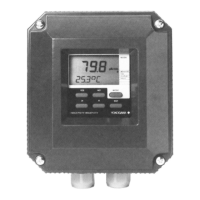
YOKOGAWA SC200 User Manual

YOKOGAWA SC200
48 pages
To Next Page IconTo Next Page
Page #1 background imageLoading...
Page #1 background image
Instruction
Manual
Model SC200
2-wire Conductivity
or Resistivity transmitter
IM 12D7B2-E-H
4th edition

Table of Contents

Questions and Answers:

YOKOGAWA SC200 Specifications

General IconGeneral
ModelSC200
TypeTransmitter
DisplayLCD with backlight
Input Channels2
Output Signal4-20 mA, HART
Communication ProtocolHART
Power Supply24 VDC
Process TemperatureDepends on sensor type
EnclosureIP66
MountingPipe, Wall, or Panel
AccuracyDepends on sensor
Measurement RangeDepends on sensor type and configuration

Summary

1. INTRODUCTION

1-1. Application

Describes the EXA SC200 transmitter's purpose in industrial installations.

2. SPECIFICATIONS

2-1. General specifications

Details intrinsic safety, indicating range, transmission signal, power supply, and climatic conditions.

2-2. Functional description

Explains the EXA SC200's real-time micro-controller operation and features.

3. INSTALLATION AND WIRING

3-2. Wiring of sensors

Provides general precautions, hazardous area considerations, grounding, and terminal access for sensor wiring.

3-3. Wiring of power supply

Details precautions, hazardous area installation, terminal access, and power-on procedures for the power supply.

4. COMMISSIONING

4-2. Output range adjustment

Guides through the process of adjusting the output range for the transmitter.

4-4. Temperature compensation

Details how to set up temperature compensation, including automatic and manual methods.

4-5. Sensor selection and diagnostics

Covers selecting conductivity cells, cell constants, temperature sensors, and sensor diagnostics.

5. MAINTENANCE

5-1. Calibration

Provides a step-by-step guide for calibrating the conductivity transmitter.

6. TROUBLE SHOOTING

6-2. Self diagnostics of the conductivity cell

Explains how the instrument checks the conductivity cell for faults like fouling or polarization.

6-6. Error messages and explanation

Lists error codes, their possible causes, and suggested remedies for troubleshooting.

8. CLASSIFICATION

8-1. Cenelec

Details Cenelec classification, including intrinsic safety standards and hazardous area zones.

8-2. FM

Covers FM classification, including installation requirements for hazardous locations.

9. CHANGE FROM CONDUCTIVITY TO RESISTIVITY MEASUREMENT

9-1. How to change from conductivity to resistivity measurement

Provides instructions for physically switching the instrument from conductivity to resistivity mode.

Related product manuals