EasyManua.ls Logo

YOKOGAWA EJX110A User Manual

YOKOGAWA EJX110A
57 pages
To Next Page IconTo Next Page
Page #1 background imageLoading...
Page #1 background image
Users
Manual
Contents
1. Introduction
1.1 For Safe Use of Product ..............................................2
1.2 Warranty ......................................................................4
1.3 ATEX Documentation ..................................................5
2. Handling Cautions
2.1 ModelandSpecicationsCheck .................................7
2.2 SelectingtheInstallationLocation ..............................7
2.3 PressureConnection ..................................................7
2.4 InstallationofanExplosion-ProtectedInstrument ......7
2.5 EMCConformityStandards ..................................... 27
2.6 Pressure Equipment Directive (PED) ...................... 28
2.7 Safety Requirement Standards ................................ 29
3. Installation
3.1 Mounting................................................................... 30
3.2
MountingtheDiaphragmSeals ......................................30
3.3 DiaphragmSealsInstallationConsideration ............ 31
3.4 MountingtheFlushingConnectionRing .................. 32
3.5 AfxingtheTeonFilm ............................................. 33
3.6 Rotating Transmitter Section .................................... 34
3.7 ChangingtheDirectionofIntegralIndicator............. 34
4. Installing Impulse Piping
4.1 ImpulsePipingInstallationPrecautions ................... 35
4.2 ImpulsePipingConnectionExamples ..................... 37
4.3 ProcessPipingInstallationPrecautions(EJ115) 38
5. Wiring
5.1 Wiring Precautions ................................................... 40
5.2 ConnectionsofExternalWiringtoTerminalBox ...... 40
5.3 Wiring ....................................................................... 43
5.4 RTDCableConnection(EJX910A/EJX930A) ......... 45
5.5 Grounding ................................................................ 47
5.6 PowerSupplyVoltageandLoadResistance ........... 47
6. Operation
6.1 Preparation for Starting Operation ........................... 48
6.2 Zero Point Adjustment .............................................. 48
6.3 LocalParameterSetting .......................................... 49
7. Errors and Countermeasures
EJX and EJA-E Series
Differential Pressure and
Pressure Transmitters
Installation Manual
IM01C25A01-01E
IM01C25A01-01E
12thEdition
Question and Answer IconNeed help?

Do you have a question about the YOKOGAWA EJX110A and is the answer not in the manual?

YOKOGAWA EJX110A Specifications

General IconGeneral
ModelEJX110A
CategoryDifferential Pressure Transmitter
Stability±0.1% of URL per 10 years
Ambient Temperature Limit-40 to 85 °C (-40 to 185 °F)
Operating Temperature-40 to 85 °C (-40 to 185 °F)
Storage Temperature-40 to 85 °C (-40 to 185 °F)
Output Signal4 to 20 mA, HART
Response Time90 ms (typical)
Process Connection1/2 NPT, 1/4 NPT
Process Temperature Limit-40 to 120 °C (-40 to 248 °F)
MaterialHastelloy C276, 316L SST
Protection RatingIP67
Relative Humidity0 to 100% RH

Summary

Introduction

Regarding This Manual

Details on the manual's purpose, scope, rights, and usage guidelines.

For Safe Use of Product

Crucial safety instructions for operating the instrument and system.

Warranty Information

Details concerning the warranty period and conditions for repair.

ATEX Documentation

Information on ATEX documentation availability for EU countries.

Handling Cautions

Model and Specifications Check

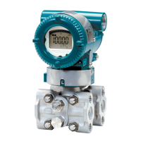
Verification of the transmitter's model name and specifications via the name plate.

Selecting the Installation Location

Guidelines for choosing an optimal installation site considering environmental factors.

Pressure Connection Precautions

Critical warnings and precautions for making pressure connections to the transmitter.

Installation of Explosion-Protected Instruments

Specific procedures and warnings for installing explosion-protected instruments.

FM Approval Standards

Details on FM approval for intrinsically safe and nonincendive types of transmitters.

CSA Certification

Information on CSA certification for intrinsically safe, nonincendive, and explosionproof types.

ATEX Certification

Technical data and requirements for ATEX certification types.

IECEx Certification

Details on IECEx certification for various hazardous location types.

Installation

Mounting the Transmitter

Instructions for mounting the transmitter on a pipe using the supplied bracket.

Mounting Diaphragm Seals

Important considerations and procedures for installing diaphragm seals.

Diaphragm Seals Installation Consideration

Key points for correct diaphragm seal installation, especially for tank level measurement.

Mounting the Flushing Connection Ring

Procedure for mounting the flushing connection ring to the pressure detector section.

Affixing the Teflon Film

Steps for applying the Teflon film and fluorinated oil before mounting.

Rotating Transmitter Section

Instructions on how to rotate the transmitter section for optimal positioning.

Changing the Direction of Integral Indicator

Procedure for changing the orientation of the integral indicator.

Installing Impulse Piping

Impulse Piping Installation Precautions

General precautions for installing impulse piping to ensure accurate pressure measurement.

Routing the Impulse Piping

Guidelines for routing impulse piping based on fluid type and process conditions.

Impulse Piping Connection Examples

Typical examples of impulse piping connections for various transmitter types.

Wiring

Wiring Precautions

Essential precautions to follow during wiring to ensure safety and performance.

Connections to Terminal Box

Detailed wiring connections for different output types and terminal configurations.

Power Supply Wiring

Instructions for connecting the power supply to the transmitter.

RTD Cable Connection

Procedures for connecting RTD cables for external temperature measurement.

Grounding

Requirements and methods for proper grounding of the transmitter.

Power Supply Voltage and Load Resistance

Guidelines for selecting power supply voltage and load resistance for the loop.

Operation

Preparation for Starting Operation

Steps to confirm the transmitter is operating properly before starting.

Zero Point Adjustment

Procedures for adjusting the zero point of the transmitter.

Local Parameter Setting

Instructions for setting transmitter parameters locally using buttons and screws.

Errors and Countermeasures

Alarm Message Summary

Summary of alarm messages, causes, output operations, and countermeasures.