<5. Wiring>
47
IM01C25A01-01E
5.4.3 Cable Connection RTD Terminal Box
Side
EJXmultivariabletransmitterRTDI/Fisfor3-wireType
RTD,Pt100.
HeedthefollowingwhenwiringanRTDofthe2-or4-wire
type.
NOTE
Pleasenotethatatemperatureerrorwilloccurwhen
youusea2-wireRTDbecauseofwiringresistance.
PleasedonotgroundtheshieldontheRTDsideof
thecable.
CAUTION
Pleaseuseonlythecablesprovidedwiththis
instrument.
Whenwiring,besurenottodamagethecable's
insulation or its core.
Allthecablecoresmusthavesufcientinsulation
aroundthem.
Donotletthesignallinecontacttheshieldline.
Donotallowtheshieldlineorthesignallinetocome
theearthpotentialvoltage.
2-Wire 3-W ire 4-Wire
A
B A B b
A
B ba
F0524.ai
Figure 5.18 The Method of Wiring for the RTD Side
Table 5.2 The Method of Wiring for the RTD Side
RTD Terminal
RTD Terminal A a B b
2-Wire White - Blue1andBlue2 -
3-Wire White - Blue1 Blue2
4-Wire White open Blue1 Blue2
NOTE
Thecolordisplayinthetableshowsthewhitelineof
thecable.
Thecablecolorcouldchangedependingonthecable
type.
Blue1andblue2allowchangingplaces.
For2-wireType,connecteitherwhichisblue1or
blue2,andgiveothersideasOPEN.
5.5 Grounding
Groundingisalwaysrequiredfortheproperoperationof
transmitters.Followthedomesticelectricalrequirements
asregulatedineachcountry.Foratransmitterwitha
built-inlightningprotector,groundingshouldsatisfy
groundresistanceof10Ωorless.
Groundterminalsarelocatedontheinsideandoutsideof
theterminalbox.Eitheroftheseterminalsmaybeused.
Ground terminal
(inside)
Ground terminal
(outside)
F0525.ai
Figure 5.19 Ground Terminals
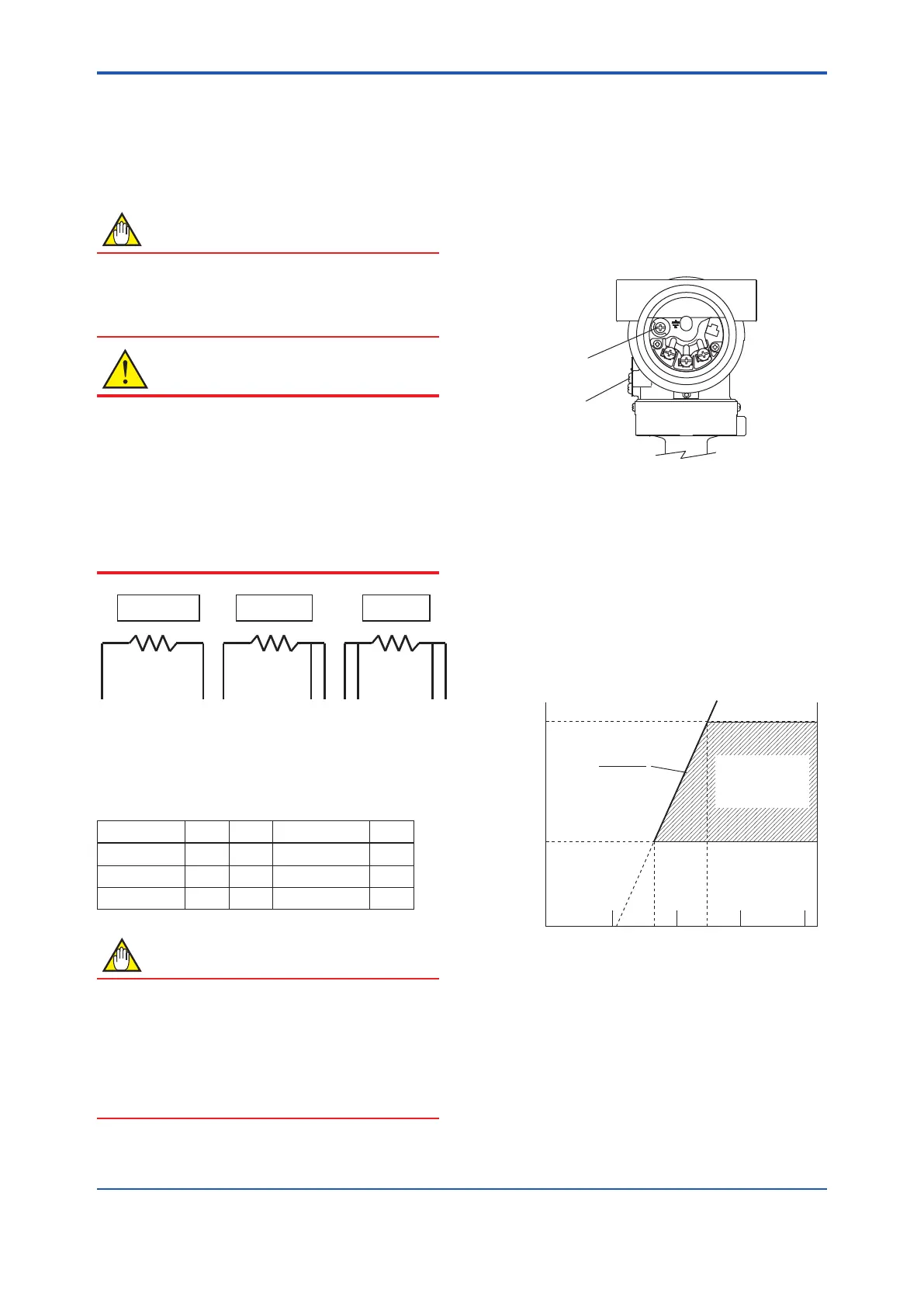
5.6 Power Supply Voltage and
Load Resistance
For 4 to 20 mA output only.
Whenconguringtheloop,makesurethattheexternal
loadresistanceiswithintherangeinthegurebelow.
(Note) Incaseofanintrinsicallysafetransmitter,externalload
resistanceincludessafetybarrierresistance.
600
250
0 10.5 16.6 25.2 42
External
load
resistance
R (Ω)
Power supply voltage E (V DC)
F0526.ai
Communication
applicable range
BRAIN and HART
R=
E–10.5
0.0244
Figure 5.20 Relationship between Power Supply
Voltage and External Load Resistance

 Loading...


