IM 12D7B2-E-H
38
The EXA SC200 can be used for both con-
ductivity and resistivity measurement. As
delivered the instrument is set for conducti-
vity measurement.
9-1. How to change from conductivity to
resistivity measurement
- Remove the cover after loosening the 4
screws. Now you have access to the Dis-
play Board.
- Loosen the 4 screws that hold this board
in place and remove it from the enclosure.
- On the upper back side of the Display
Board are 5 blue jumpers. Change the
spring jumper as shown in the figure.
Make sure that center contact spring is
securely hold to have good contact.
Within 15 seconds after the jumper change,
the EXA SC200 will automatically load de-
fault data for resistivity measurement.
The SC200 transmitter can be reassembled
now, following the opposite sequence as
described above.
9-2.Resistivity measurement
As a resistivity measuring transmitter the
EXA SC200 has the same function as
described earlier in this manual.
The units mS/cm and µS/cm are replaced
by kΩ.cm and MΩ.cm for resistivity meas-
urement. If no unit is shown the unit is Ω.cm
and can be changed in kΩ.cm by the key
if the “.” is flashing. See range adjustment in
section 4-2.
9. CHANGE FROM CONDUCTIVITY TO
RESISTIVITY MEASUREMENT
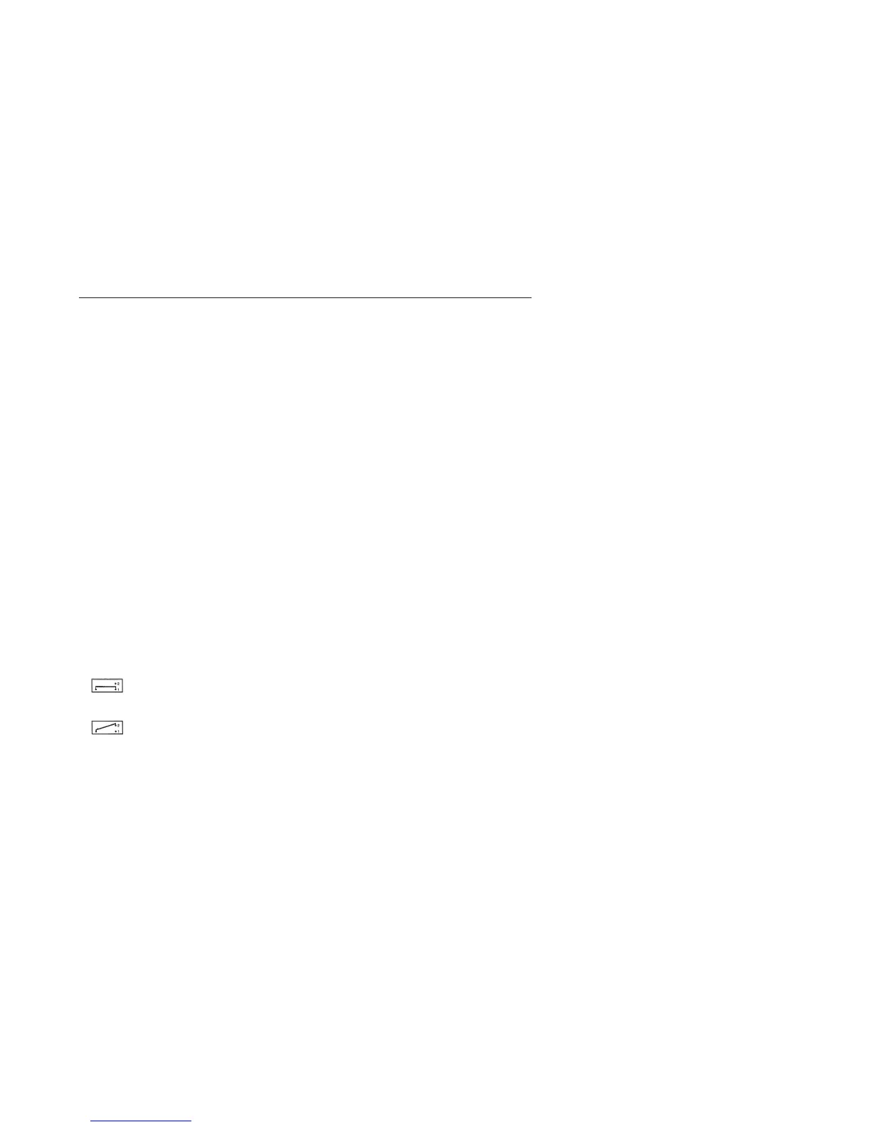
from
position for conductivity
measurement
to
position for resistivity
measurement
9-3.Maintenance of the transmitter
Calibration of the resistivity transmitter is
done in the same way as described in sec-
tion 5-1.
The calibration values can be calculated as
follows:
kΩ.cm = 1000 µS/cm
Ω.cm = 1000 mS/cm
Example:
The 0.001 % NaCI-solution has a conducti-
vity value of 21.4 µS/cm. In resistivity mode
the value is 1000/21.4 = 46.7 kΩ.cm.

 Loading...


