<6. Maintenance>
6-1
IM 01C50G01-01EN
6. Maintenance
6.1 General
Each component of this instrument is congured in
units to make maintenance easier.
This chapter contains disassembly and assembly
procedures associated with calibration, adjustment
and part replacement required for maintenance of
the affected instrument.
IMPORTANT
1. Maintenance of this instrument should be
performed in a service shop where the
necessary tools are provided.
2. Handling the MAIN and Indicator assembly
Some of the parts contained in the MAIN
and Indicator assembly are susceptible to
static electricity damage. Before performing
maintenance, use a ground wrist band
or other antistatic measures, and avoid
touching the electronic components and
circuits with bare hands.
6.2 Calibration
This instrument is fully factory-tested and is
guaranteed for the intended accuracy, eliminating
the need for calibration. When calibration needs to
be varied, the following equipment and calibration
procedure is recommended.
6.2.1 Selection of Equipment for
Calibration
Table 6.1 lists the equipment required for
calibration. The calibration equipment traceable to a
verifying agency standard should be used.
6.2.2 Calibration Procedure
To conduct calibration required to evaluate the
uncertainty while using the instrument, follow the
steps below:
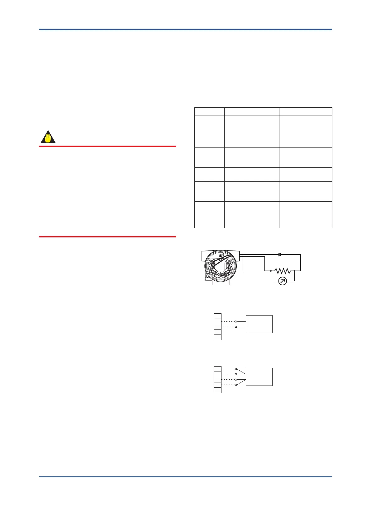
1. In accordance with the example wiring shown in
Figure 6.1, connect each equipment and initiate
warm up. Lay wiring on the input side according
to the sensor to be used.
Table 6.1 Calibration Equipment List
Name Recommended Remark
Power
supply
SDBT, SDBS
distributor
4 to 20mA DC
(Output voltage:
26.5±1.5V DC, drop
by internal 250Ω
resistance included)
Load
resistance
2792 standard
resistor
(250Ω ±0.005%)
For 4 to 20mA DC
Voltmeter For 4 to 20mA DC
signal
Universal
calibrator
For calibration of
DC voltage and
thermocouple
Variable
resistor
279301 6-dial
variable resistor
(accuracy: ±0.01%
±2mΩ)
For calibration of
RTD input
F0601.ai
1
2
3
4
5
1
2
3
4
5
(A)
(B)
(B)
(A)
a. Wiring of power supply and output
b. Example of wiring for thermocouple or DC voltage input
(when 1 input type is used)
+ Output signal
– Load
resistance
DC voltage generator
Voltmeter
c. Example of wiring for RTD 4-core type
(when 1 input type is used)
Variable resistor
(+)
(–)
Figure 6.1 Example of Wiring for Calibration
Equipment

 Loading...


