<6. Maintenance>
6-6
IM 01C50G01-01EN
6.5 Integral Indicator and Error Display
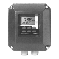
For temperature transmitters equipped with an integral indicator, errors in the temperature sensor or the
transmitter cause an integral indicator to call up the applicable error code. Table 6.5 lists the error codes for
HART and BRAIN. Table 6.7 lists the error codes for Foundation eldbus.
Table 6.5 List of Error Codes (HART and BRAIN)
Alarm
Number
Indicator
Message
Cause Output operation during error
AL.00 CPU.ERR MAIN CPU failed According to the transmitter failure
output (burnout)
Communacation disabled
AL.01 SENSOR Sensor non-volatile memory veries alarm According to the transmitter failure
output (burnout)
Communication enabled
AL.02 TMP.MEM Non-volatile memory of the TEMP ASSY verify alarm
AL.03 AD.CONV Input circuit hardware failed
AL.04 CAL.ERR MAIN ASSY memory failed
AL.05 CAL.ERR TEMP ASSY memory failed
AL.06 TMP.ERR TEMP ASSY voltage failed
AL.07 COM.EEP Communication non-volatile memory veries alarm
AL.08 TMP.MEM Non-volatile memory of the TEMP ASSY veries
alarm
Continue to operate and output
AL.09 COM.ERR Internal communication failed According to the transmitter failure
output (burnout)
Communication enabled
AL.10 S.1.FAIL Sensor 1 failed or disconnected from terminal block Refar table 6.6
AL.11 S.2.FAIL Sensor 2 failed or disconnected from terminal block Refar table 6.6
AL.12
*1
S.1.SHRT Sensor 1 short-circuited Refar table 6.6
AL.13
*1
S.2.SHRT Sensor 2 short-circuited Refar table 6.6
AL.14
*1
S.1.CORR Sensor 1 corroded Continue to operate and output
AL.15
*1
S.2.CORR Sensor 2 corroded Continue to operate and output
AL.20 S.1.SGNL Sensor 1 input is out of measurable range. Continue to operate and output
AL.21 S.2.SGNL Sensor 2 input is out of measurable range. Continue to operate and output
AL.22 TERMNL Terminal block temperature is abnormal. Or terminal
block temperature sensor failed
Refar table 6.6
AL.23 S.1.FAIL During sensor backup operation, Sensor1 fails, it
has output Sensor2
Operating to the backup side.
When the backup side also fails,
output is according to burnout setting.
AL.24 S.2.FAIL During sensor backup operation, Sensor2 fails Continue to operate and output
AL.25 DRIFT Sensor drift Continue to operate and output
AL.26
*1
S.1.CYCL Temperature cycling times of Sensor1 exceeds the
threshold
Continue to operate and output
AL.27
*1
S.2.CYCL Temperature cycling times of Sensor2 exceeds the
threshold
Continue to operate and output
AL.30 PV LO PV value is below the range limit setting Lower limit 3.68mA (-2%)
AL.31 PV HI PV value is above the range limit setting Upper limit 20.8mA (105%)
AL.40 S.1 LO Measured temperature of sensor 1 is too low Continue to operate and output
AL.41 S.1 HI Measured temperature of sensor 1 is too high Continue to operate and output
AL.42 S.2 LO Measured temperature of sensor 2 is too low Continue to operate and output
AL.43 S.2 HI Measured temperature of sensor 2 is too high Continue to operate and output
AL.44 AMBNT.L Ambient temperature is below-40 degree C Continue to operate and output
AL.45 AMBNT.H Ambient temperature is above 85 degree C Continue to operate and output
AL.50 LRV LO LRV setting is below the sensor operating
temperature range
Continue to operate and output

 Loading...


