<7. General Specications>
7-24
IM 01C50G01-01EN
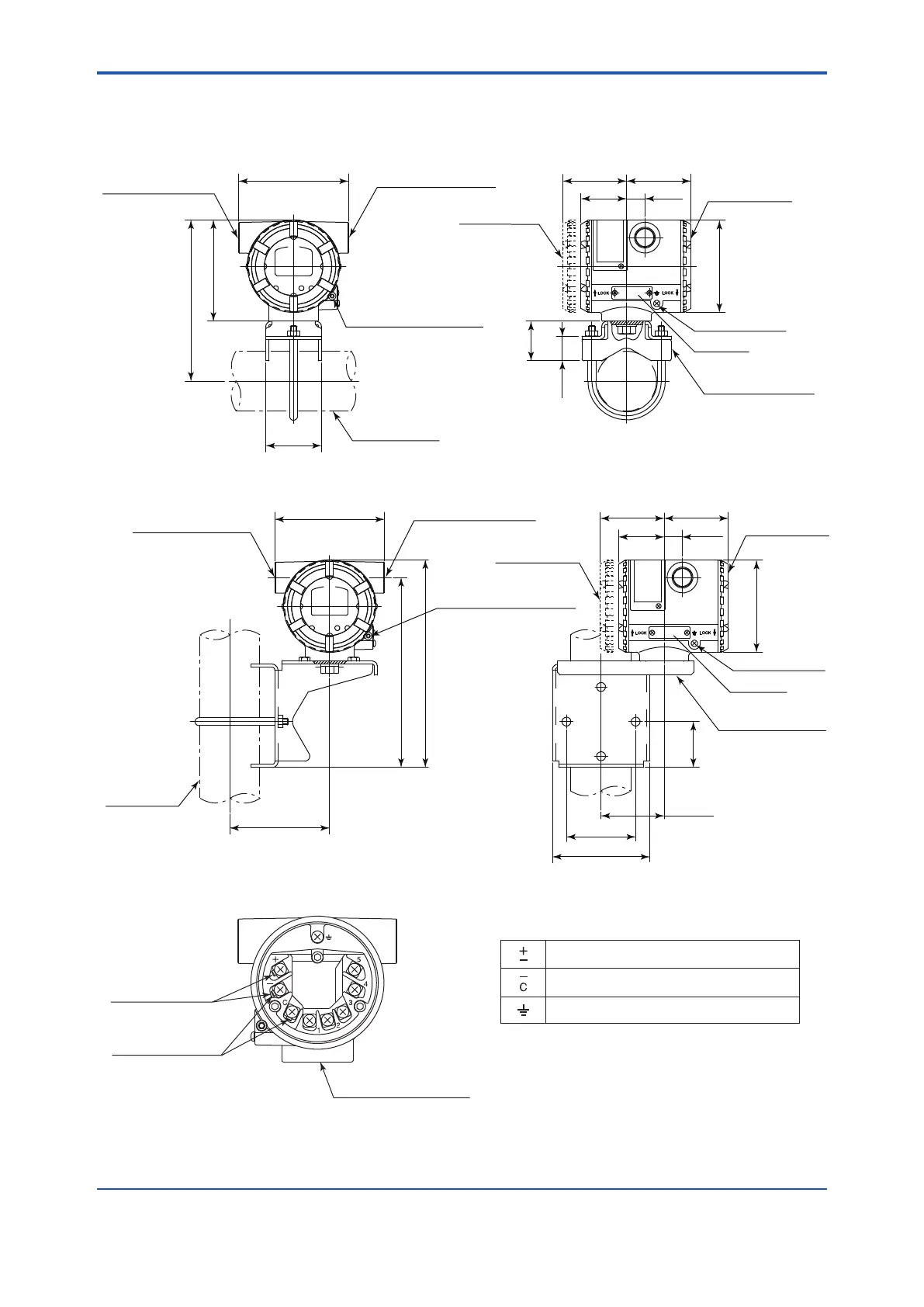
7.4 Dimensions (YTA610 and YTA710)
65.4(2.57)
With Indicator
(Optional)
Tag Plate
Terminal Cover
Electrical Connection
(Output signal)
Electrical Connection
(Input signal)
Ground Terminal
18.5
(0.73)
47.1
(1.85)
66.1(2.60)
ø93(3.66)
111(4.37)
56(2.21)
102(4.02)
164(6.46)
Shrouding Bolt
(For Explosionproof type)
25
(0.98)
40
(1.57)
2-inch horizontal pipe mounting
2-inch vertical pipe mounting
2-inch pipe
ø60.5(ø2.38)
Horizontal Pipe
Mounting Bracket
(Optional)
Electrical Connection
(Output signal)
Electrical Connection
(Input signal)
2-inch pipe
ø60.5(ø2.38)
111(4.37)
101(3.98)
191.5(7.54)
209.5(8.25)
Shrouding Bolt
(For Explosionproof type)
65.4(2.57)
Tag Plate
Terminal Cover
Ground Terminal
Vertical Pipe
Mounting Bracket
(Optional)
18.5
(0.73)
47.1
(1.85)
46
(1.81)
64(2.52)
98(3.86)
66.1(2.60)
ø93(3.66)
70(2.76)
With Indicator
(Optional)
F0703.ai
Unit: mm (Approx. inch)
Terminals
F0704.ai
Terminal Configuration
Power supply and output terminal
External indicator (ammeter) termial
*1
Ground terminal
Communication
Terminals
Connection hook
CHECK METER
Connection hook
*1
M10×1.5 12-deep female
for mounting bracket
*1 : When using an external indicator or a check meter,
the internal resistance must be 10Ω or less.
The hook is not available for Fieldbus
communication type.

 Loading...


