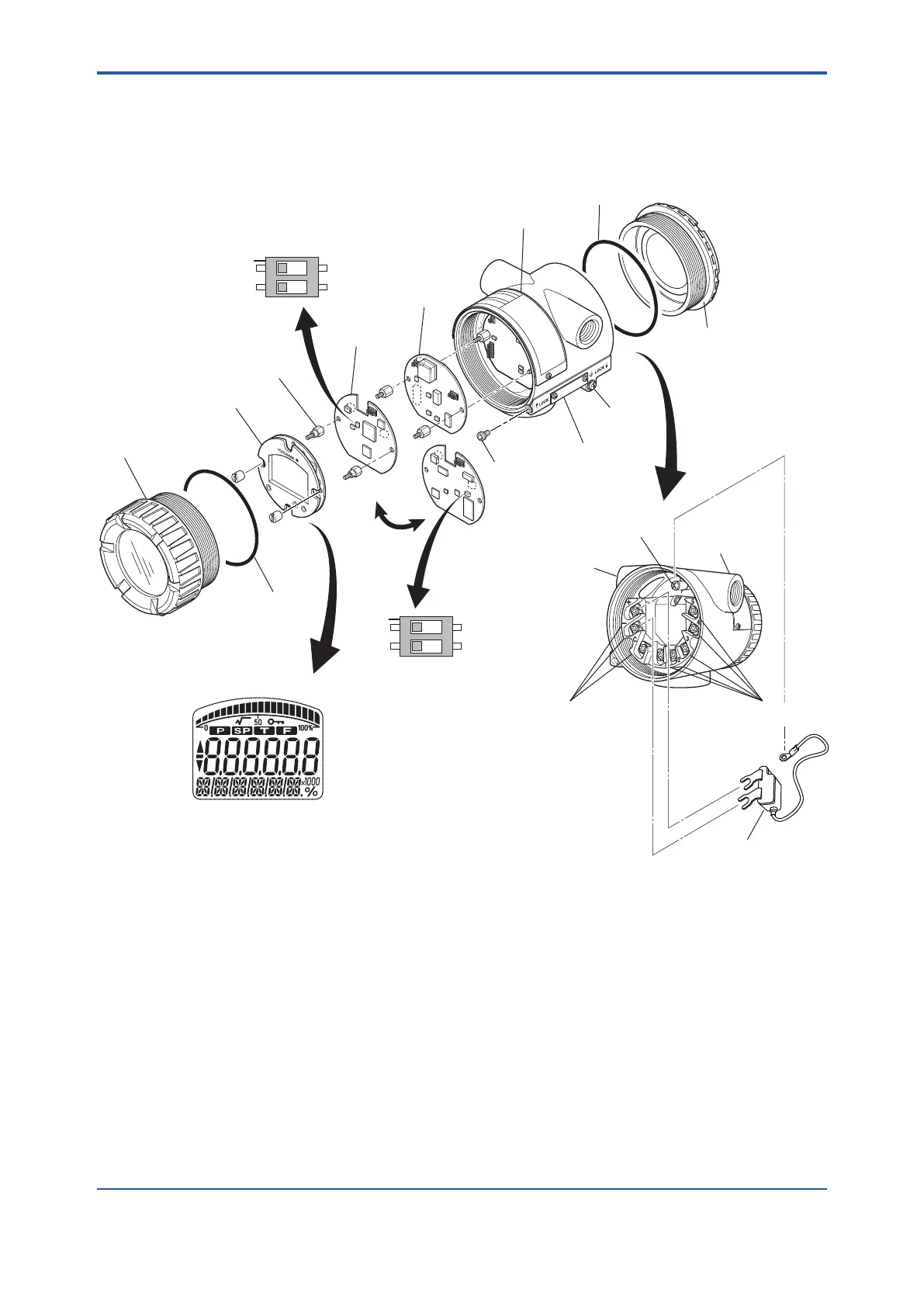
<3. Part Names and Functions>
3-1
IM 01C50G01-01EN
3. Part Names and Functions
3.1 Part Names
F0301.ai
SW1
BOUT
WP
O
N
1
2
SIMULATE_ENABLE switch
Write lock switch
(HART/BRAIN)
TEMP assembly
Stud bolt
Name plate
Grounding
terminal
Terminal cover
Grounding
terminal
Wiring connector
(input signal side)
Output signal terminal
Wiring connector
(output signal side)
Input signal terminal
Tag plate
Lock screw
(for ATEX and IECEx
flameproof type)
Integral indicator display
Indicator assembly
MAIN assembly
Burn out output direction
setting switch upon hardware failure
O-ring
O-ring
Lightning protector
SW2
SIM
WP
O
N
1
2
(FF)
Figure 3.1 Part Names
3.2 Hardware Error Burnout
and Hardware Write Protect
Switch
There are two slide switches on the MAIN
assembly board. One sets the hardware error
burnout direction, and the other sets a hardware
write protection function which disables parameter
changes through the use of a handheld terminal or
some other communication method.

 Loading...


