<5. Wiring>
5-3
IM 01C50G01-01EN
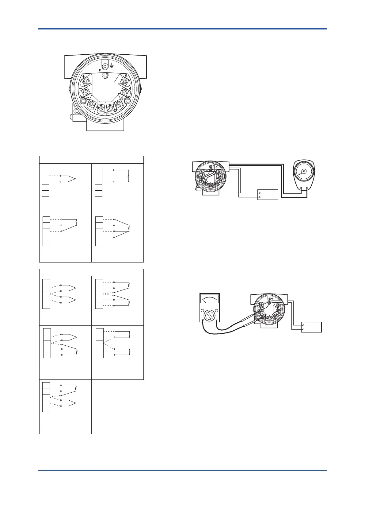
The temperature sensor is to be
connected as shown in Figures 5.5.
F0504.ai
Figure 5.4 Terminal Diagram
(B1)
(A1)
1
2
3
4
5
(–)
(+)
1
2
3
4
5
(B1)
(B1)
1
2
3
4
5
(–)
(+)
1
2
3
4
5
(+)
(A1)
(B2)
(B2)
(A2)
(A2)
(B2)
(B2)
(B2)
(A2)
1
2
3
4
5
1
2
3
4
5
1
2
3
4
5
1
2
3
4
5
(–)
(+)
(B)
(A)
(B)
(B)
(B)
(A)
(A)
(A)
(B)
Thermocouple and
DC voltage
RTD and resistance
(3-wire)
Thermocouple +
RTD and resistance
(3-wire)
(–)
1
2
3
4
5
(+)
RTD and resistance
(3-wire)
+ Thermocouple
RTD and resistance
(2-wire)
Dual input
Thermocouple and
DC voltage
RTD and resistance
(2-wire)
RTD and resistance
(3-wire)
RTD and resistance
(4-wire)
Single input
F0505.ai
(B1)
(B1)
(A1)
Figure 5.5 Wiring Connection Diagram
5.4.2 Output Terminal Connection
(1) Connection of output signal/power supply
cable
Connect the output signal cable (shared with the
power supply cable) to the – terminal and the +
terminal. For details, refer to Figure 5.1, “Loop
construction”.
(2) Connectionofwiringforeldindicator
Connect the lead wire for the eld indicator with the
– terminal and the C terminal.
Note: Use a eld indicator with an internal resistance of 10Ω or
less.
F0506.ai
Field indicator
Power
supply
–
–
+
+
Figure 5.6 Connection to Field Indicator
(3) Connectionofcheckmeter
Connect the check meter with the – terminal and
the C terminal.
The current signal of output signal 4 to 20 mA DC is
output from the – terminal and the C terminal.
Note: Use a check meter with internal resistance of 10Ω or less.
F0507.ai
Check meter
+
–
Power
supply
Figure5.7 CheckMeterConnection

 Loading...


