<6. Maintenance>
6-3
IM 01C50G01-01EN
F0602.ai
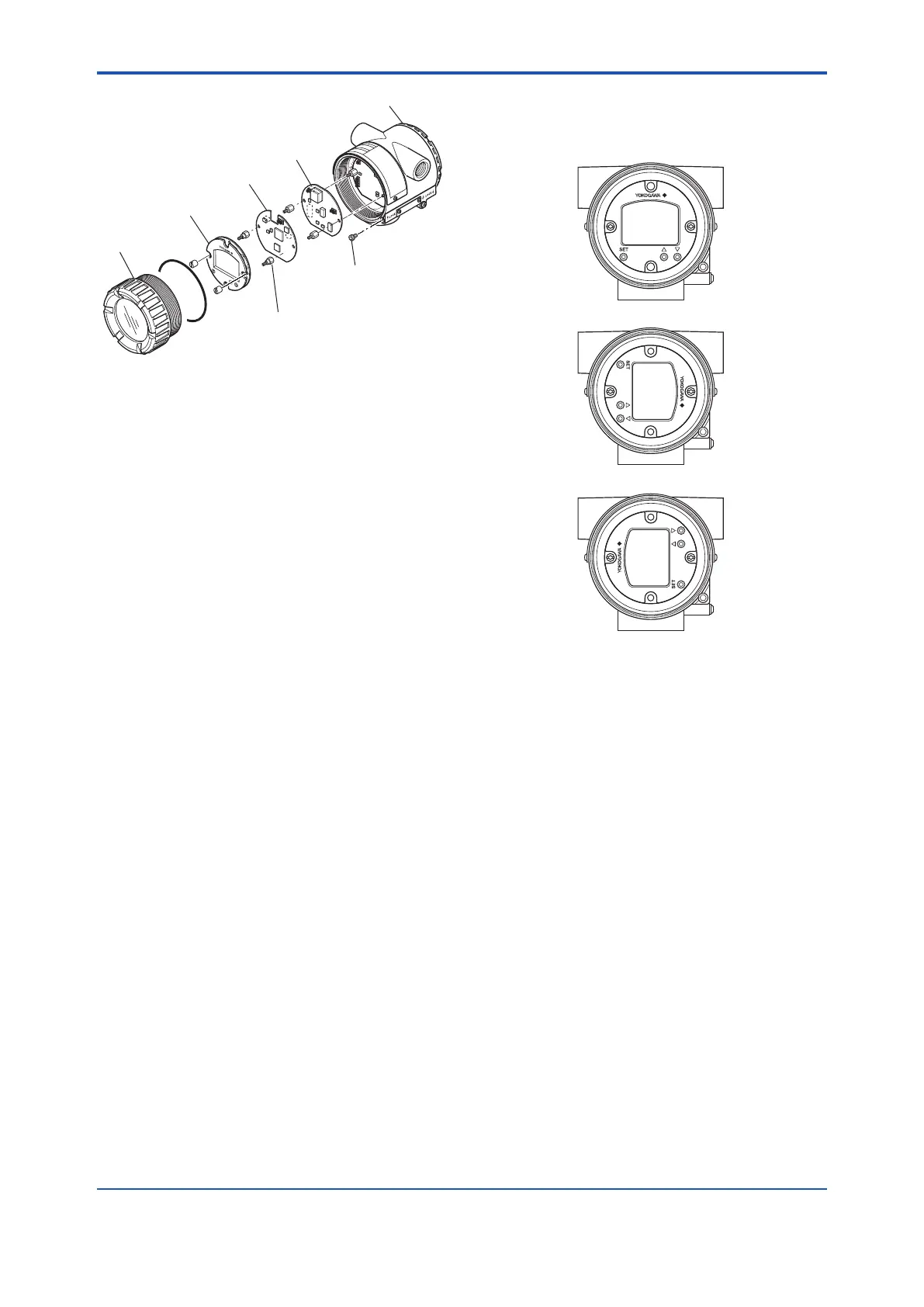
Amplifer cover
TEMP assembly
Stud bolt
Terminal cover
Lock screw
(for ATEX and IECEx
flameproof type)
Indicator assembly
MAIN assembly
Figure 6.2 Mounting and Removal of Integral
Indicator Assembly
6.3.1 Replacement of Integral Indicator
Removal of integral indicator
1. Remove the cover.
2. Remove two mounting screws while using your
hand to support the integral indicator.
3. Remove the indicator assembly from the
MAIN assembly. At this time, straighten and
pull the indicator assembly forward so that the
connector connecting the MAIN assembly and
the indicator assembly is not damaged.
Mounting the Integral indicator
Integral Indicator can be installed in the following
three directions.
F0603.ai
Figure 6.3 Installation Direction of Indicator
1. Place the Indicator assembly in desired
direction over the MAIN assembly.
2. Align the mounting hole of the Indicator
assembly with the stud bolt hole, and carefully
insert the indicator into the connector in a
straight manner so that the connector is not
damaged.
3. Tighten the two mounting screws that secure
the indicator.
4. Mount the cover.

 Loading...


