<6. Maintenance>
6-7
IM 01C50G01-01EN
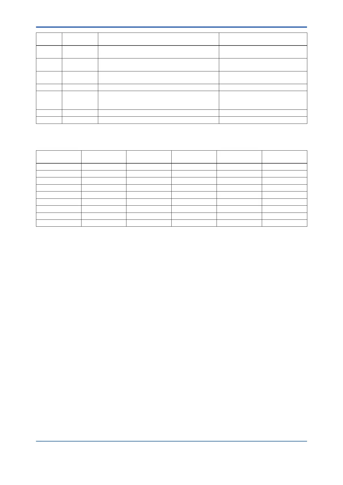
Alarm
Number
Indicator
Message
Cause Output operation during error
AL.51 LRV HI LRV setting is above the sensor operating
temperature range
Continue to operate and output
AL.52 URV LO URV setting is below the sensor operating
temperature range
Continue to operate and output
AL.53 URV HI URV setting is above the sensor operating
temperature range
Continue to operate and output
AL.54 SPAN.LO It is set below recommended minimum span Continue to operate and output
AL.60 PV.CFG There is a setting error in the sensor that is mapped
to the PV
Hold the output of the previous error
When it occurs at startup, hold at
4mA
AL.61 S.1 CFG There is a false set to sensor1 Continue to operate and output
AL.62 S.2 CFG There is a false set to sensor2 Continue to operate and output
*1: Applicable only for YTA710.
Table 6.6 Output operation (HART and BRAIN)
Current output
mapping
S.1.FAIL S.2.FAIL S.1.SHRT
*3
S.2.SHRT
*3
TERMNL
SENS.1 Sensor Burnout *1 Sensor Burnout *1 *1
S.1-TER Sensor Burnout *1 Sensor Burnout *1 Sensor Burnout
TERM *1 *1 *1 *1 Sensor Burnout
SENS.2 *1 Sensor Burnout *1 Sensor Burnout *1
S.2-TER *1 Sensor Burnout *1 Sensor Burnout Sensor Burnout
S.1-S.2 Sensor Burnout Sensor Burnout Sensor Burnout Sensor Burnout *1
S.2-S.1 Sensor Burnout Sensor Burnout Sensor Burnout Sensor Burnout *1
AVG Sensor Burnout Sensor Burnout Sensor Burnout Sensor Burnout *1
BACKUP *2 *2 *2 *2 *1
*1: Continue to operate and output.
*2: When both sensor1 and sensor2 occur error, output is burnout.
*3: Applicable only for YTA710.

 Loading...


