<3. Parameter Setting>
3-22
IM 01C25T01-06EN
3.3.10 Software Write Protection
The transmitter congured data is saved by using a
write protection function. The write protection status
is set to “Yes” when 8 alphanumeric characters are
entered in the New password eld and transferred
to the transmitter.
When write protection is set to ”Yes,” the transmitter
does not accept parameter changes. When the
same eight alphanumeric string entered in the New
password eld is also entered in the Enable wrt
10min eld and transferred to the transmitter, it
will be possible to change transmitter parameters
during a 10 minute period.
To change the transmitter from the write protection
”Yes” status back to write protection ”No” status,
use Enable wrt 10min to rst release the write
protection function and then enter eight spaces in
the New password eld.
• Procedure to call up the display using by DD
and DTM (excluding EJX HART 5 DTM based
on FDT1.2)
DD and DTM
(excluding EJX_
HART 5[1.2])
[Root Menu] → Detailed setup
→ Device information → Field
device info → Wrt protect menu
→
→ Write protect Display current protect mode
(Yes: protected, No: not
protected)
→ Enable wrt 10
min
Release the protect function for
10 min.
→ New password Set the new password or change
the password
• Procedure to call up the display by EJX HART 5
DTM based on FDT1.2
EJX HART 5
DTM based on
FDT1.2
Write Protect →
→ Write Protect Display current protect mode
(Yes: protected, No: not protected)
→ Enter new
password
Enter the password here to enable
the protect function.
Enter eight spaces to disable the
protect function.
→ Enable write Enter the password here to release
the protect function for 10 min.
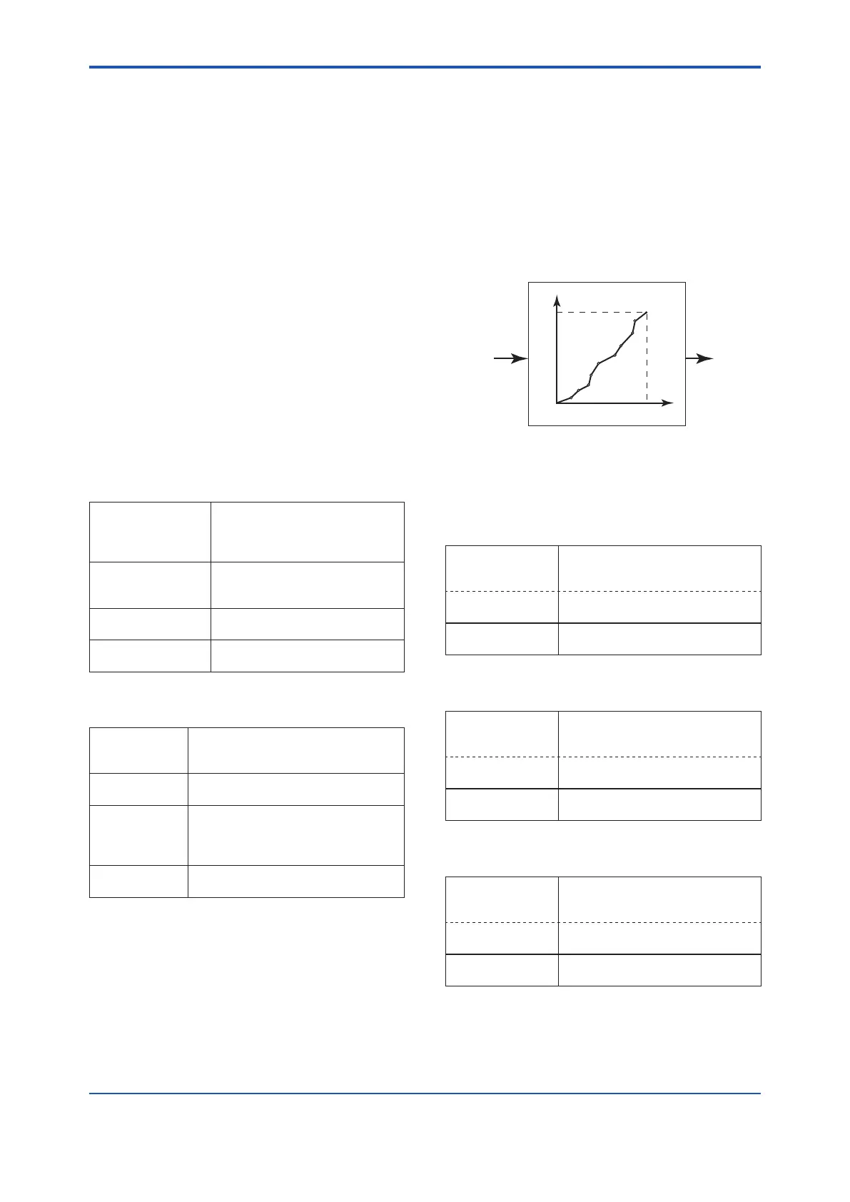
3.3.11 Signal Characterizer
This function is used to compensate the output for
non-linear applications. The characterized values
are applied to the analog output. For the measured
pressure, a maximum of nine coordinates can be
specied between 0-100%. Perform the coordinate
settings while the S.C. at S.C. menu parameter is
“Disabled”.
To apply the settings to the output, set the S.C.
parameter to “Enabled”.
Note that the transmitter rejects the activation of the
function by AL. 60 with the following transmitter’s
status:
• When the specied coordinates of x and y are
not incremental as the input increases.
• When the output mode of the output signal is
set as “Sq root”; at the same time, the low cut
mode is set to “Linear”.
F0308.ai
Y
X
100%0%
100%
INPUT
OUTPUT
Input pressure in % Characterized value
Follow the steps below to perform the signal
characterizer.
<1> Set the desired number of coordinates on the
line graph
• Procedure to call up the display
DD and DTM
(excluding EJX_
HART 5[1.2])
[Root Menu] → Detailed setup →
Signal condition → S.C. menu →
EJX_HART 5[1.2]
DTM
Conguration → Signal
Characterizer Menu →
→ Num of points Set the number between 0 and 9
<2> Set the coordinates
• Procedure to call up the display
DD and DTM
(excluding EJX_
HART 5[1.2])
[Root Menu] → Detailed setup →
Signal condition → S.C. menu →
EJX_HART 5[1.2]
DTM
Conguration → Signal
Characterizer Menu →
→ Point setting Set the coordinates (X-axis,
Y-axis)
<3> Apply the settings
• Procedure to call up the display
DD and DTM
(excluding EJX_
HART 5[1.2])
[Root Menu] → Detailed setup →
Signal condition → S.C. menu →
EJX_HART 5[1.2]
DTM
Conguration → Signal
Characterizer Menu →
→ S.C. Select “Enabled” or “Disabled”

 Loading...


