<3. Parameter Setting>
3-25
IM 01C25T01-06EN
3.3.14 CapillaryFillFluidDensity
Compensation
For transmitters with diaphragm seals, this function
is used to compensate the zero shift caused by the
ambient temperature eect on the capillary tubes.
The following equation indicates the relationship
between the calculated output value and the
compensating constant K (%/°C) with the measured
ambient temperature at the capsule module.
Compensated output = output + K × Temp
(1) Temperature Compensation Mode Setup
When using this function, set T.Z. Cmp mode
to “On” to enable or “O” to disable. To set to
“On”, follow the procedure below.
• Procedure to call up the display
DD and DTM
(excluding EJX_
HART 5[1.2])
[Root Menu] → Detailed setup
→ Signal condition → T.Z.
Comp menu →
EJX_HART 5[1.2]
DTM
Conguration → Pressure
Sensor →
→ T.Z. Comp mode Select “On” or “O”
Select “On” at the T.Z. Cmp mode display
(2) Zero Shift Compensation Setup
Obtain the K compensating value from the
equation (a) below, and enter the value to Temp
Zero.
K= ×100.............. (a)
– h×B
Span
where,
B: Constant value of ll uid (See Table A.)
Span: |URV – LRV|
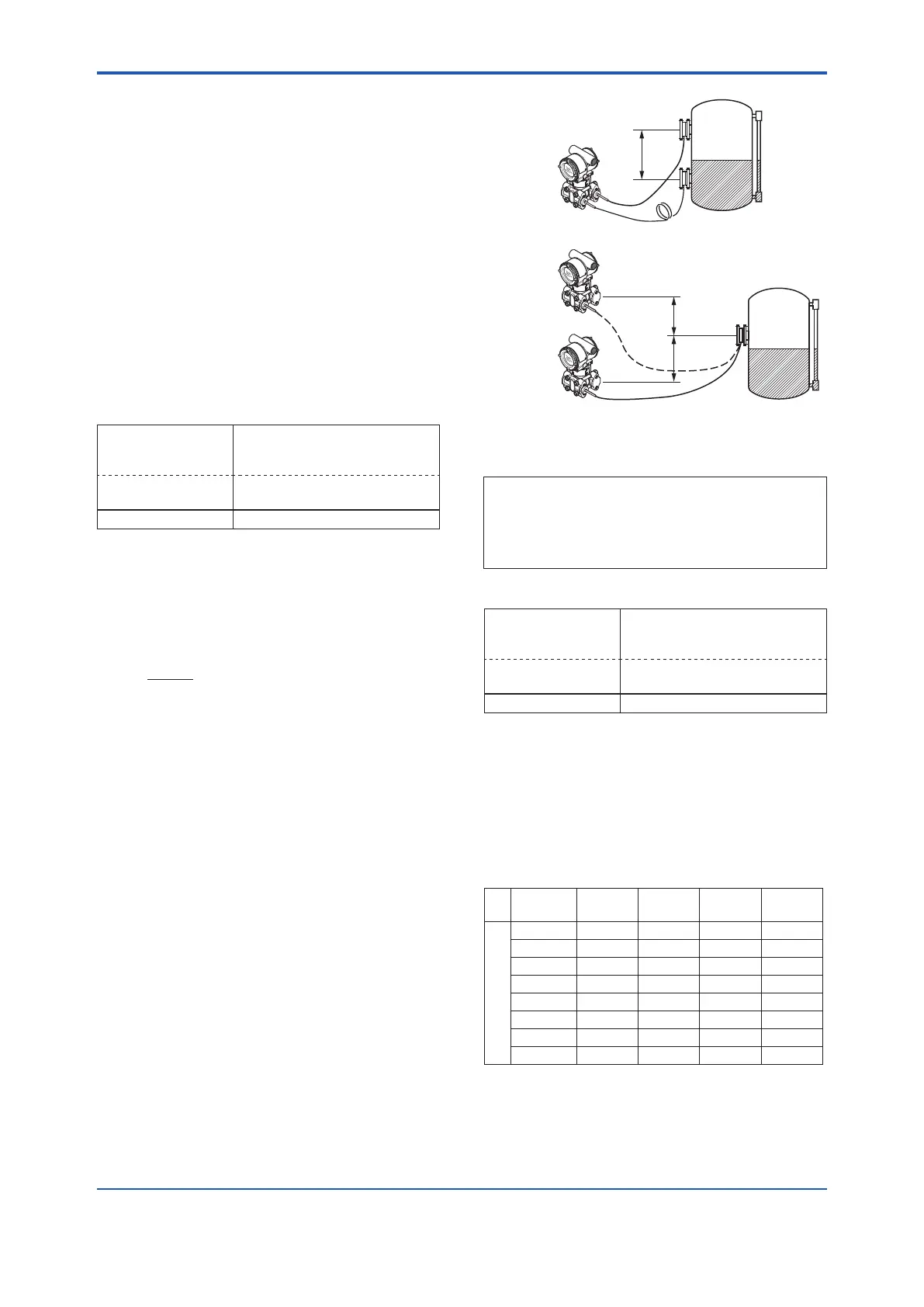
h: Distance from high pressure side to low
pressure side (m)
EJX118A/EJA118E: Distance from high side
of diaphragm seal to low side of diaphragm
seal.
EJX438A/EJA438E: Distance from
diaphragm seal (high side) to position of
transmitter (low side).
Transmitter
L
h
0
H
(+)
● EJX118A/EJA118E
F0310.ai
h
h
L
L
H
Transmitter
Transmitter
0
(+)
(–)
● EJX438A/EJA438E
Note: When the transmitter is positioned lower than the
diaphragm seal part, the value of “h” must have a
negative sign (–).
Example: Enter K value obtained from the equation (a).
A value haivng up to 3 decimal places may be
specied.
When h=+3 m, Fill uid code A, span=15 kPa,
K=−(+3)×0.00745÷15×100=−0.149
• Procedure to call up the display
DD and DTM
(excluding EJX_
HART 5[1.2])
[Root Menu] → Detailed setup
→ Signal condition → T.Z.
Comp menu →
EJX_HART 5[1.2]
DTM
Conguration → Pressure
Sensor →
→ Temp Zero Set the compensation value
Input “-0.149” to Temp Zero prameter.
Note 1: The function is performed using a built-in temperature
sensor in the transmitter body. The temperature
deviation between the transmitter body and capillaries
should be minimized to achieve optimal performance
of the function.
Note 2: When the span changes, reenter the newly obtained
value of K to Temp Zero.
Table A. Constant value [B] of ll uid
Filluid
code
A, C,
1, 2, 4
B D E
Constant value [B]
mmH2O 0.76 0.87 1.45 0.75
kgf/cm
2
0.000076 0.000087 0.000145 0.000075
kPa 0.00745 0.00853 0.01422 0.00736
mBar 0.07453 0.08532 0.14220 0.07355
atm 0.000074 0.000084 0.000140 0.000073
inH2O 0.02992 0.03425 0.05709 0.02953
psi 0.00108 0.00124 0.00206 0.00167
mmHg 0.05592 0.06401 0.10669 0.05518
Note 3: Select the unit of constant value of [B] from the actual
unit used for the transmitter in operation.

 Loading...


