<4. Diagnostics>
4-14
IM 01C25T01-06EN
• Procedure to call up the display
DD and DTM
(excluding EJX_
HART 5[1.2])
[Root Menu] → Diag/Service →
Diag Parameters → Diag Output →
Diag Fixed Out Val →
EJX_HART 5[1.2]
DTM
Diag and Service → Advanced Diag
Congurations → Diag Fixed Out
Val →
Status Output for Advanced diagnostic
The output of the abnormal results are applicable
for a transistor output (open collector) of an on/o
signal according to the status of high and low alarm
limits, which are values set to Limit parameters as
shown in subsection 4.2.2.1. About the FlgTemp
Hi Alert Val, or FlgTempLoAlertVal for Heat
trace monitoring, refer to subsection 4.2.3.2.
DO Select
If the advanced diagnostic function is installed, the
following modes can be also assigned to the status
output in addition to Pres, SP and Temp.
Mode Function
Diag Alarm
The status regarding advanced diagnostic
masked by Diag Option is output.
All
All status of Press, SP, Temp and advanced
diagnostic are output.
Alarm Display on LCD
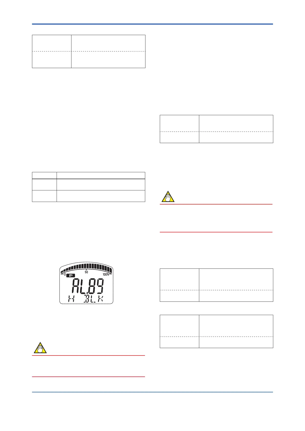
If the ILBD algorithm detects the abnormality, the
content of the detected result is displayed with
“AL.88” or “AL.89” on the LCD. “AL.88” indicates
that condition is not applicable for the abnormality
detection and “AL.89” indicates the abnormality is
detected.
F0410.ai
Figure4.7 DisplayExampleofHSideBlocking
The alarm display on LCD regarding the advanced
diagnostic is described in Table 4.5.
NOTE
The alarms of “Invalid Ref xx” and “ILBD over
range” do not link to the 4-20 mA analog signal
and Status output.
4.2.2.6 Condition Check
After the transmitter was installed, it is necessary to
conrm if Pres is stable under the normal operating
condition or if uctuation amplitude under the
normal operating condition is large enough to detect
the blockage.
Stability of Pressure Value
1) Observe the value change of Pres under the
normal operating condition for 10 minutes.
2) Conrm the value change is less than 10%.
• Procedure to call up the display
DD and DTM
(excluding EJX_
HART 5[1.2])
[Root Menu] → Detailed setup →
Sensors → Pressure Sensor →
Pres
EJX_HART 5[1.2]
DTM
Conguration → Process Input →
Pres
If the value change is more than 10%, the error
inuences pressure uctuation value so that the
blockage detection becomes impossible. Consider
the plant operating conditions.
FluctuationValue
NOTE
The blockage detection may not be carried
out correctly when pressure uctuation
amplitude especially with the pressure and level
measurement, is small.
Conrm that each value of fDP, fSPl, fSPh, and
BlkF is more than the value specied in the below
table.
• Procedure to call up the fDP, fSPl, fSPh display
DD and DTM
(excluding EJX_
HART 5[1.2])
[Root Menu] → Diag/Service
→ Diag Parameters → ILBD
parameters → Status → Fluct
Variables → fDP/fSPl/fSPh
EJX_HART 5[1.2]
DTM
Diag and Service → Advanced Diag
Variables → fDP/fSPl/fSPh
• Procedure to call up the BlkF display
DD and DTM
(excluding EJX_
HART 5[1.2])
[Root Menu] → Diag/Service
→ Diag Parameters → ILBD
parameters → Status → Diag
Variables → BlkF
EJX_HART 5[1.2]
DTM
Diag and Service → Advanced Diag
Variables → BlkF

 Loading...


