<4. Diagnostics>
4-12
IM 01C25T01-06EN
Bit
DD
(HART 5/HART 7)
DTM (HART 7)
DTM (HART 5) Category
0
Not used Not used
1
Not used Not used
2
A Blocking A Blocking
ILBD
3
Large Fluct L
Large Fluctuation
of Low Side
4
Large Fluct H
Large Fluctuation
of High Side
5
L Side Blocking Low Side Blocking
6
H Side Blocking
High Side
Blocking
7
B Blocking B Blocking
8
Invalid Ref F Invalid Ref BlkF
9
Invalid Ref SPH Invalid Ref fSPh
10
Invalid Ref SPL Invalid Ref fSPl
11
Invalid Ref DP Invalid Ref fDP
12 ILBD over range
Outside Diagnosis
Range
13
FT low alarm
Flg Temp Low
Alarm
Heat trace
monitoring
14
FT high alarm
Flg Temp High
Alarm
15 Not used Not used
Note: FT indicates the ange temperature.
ILBD over range (Outside Diagnosis
Range)
• Procedure to call up the display
DD and DTM
(excluding EJX_
HART 5[1.2])
[Root Menu] → Diag/Service
→ Diag Parameters → ILBD
Parameters → Conguration →
Diag Lim →
EJX_HART 5[1.2]
DTM
Diag and Service → Advanced Diag
Congurations → Impulse Line
Blockage Detection → Threshold →
1) Lim DPAvgmax
Lim DPAvgmax is the upper limit of the
diagnostic capability range. The limit value can
be changed when Diag Mode is “Stop”.
DPAvg indicates the ratio of the average of
dierential pressure to the EJX maximum span
regarded as 1. When DPAvg exceeds this
limit, “ILBD over range” is generated so that the
blockage detection becomes impossible.
2) Lim DPAvgmin
Lim DPAvgmin is the lower limit of the
diagnostic capability range. The limit value can
be changed when Diag Mode is “Stop”.
When DPAvg is below this limit, “ILBD over
range” is generated so that the blockage
detection becomes impossible.
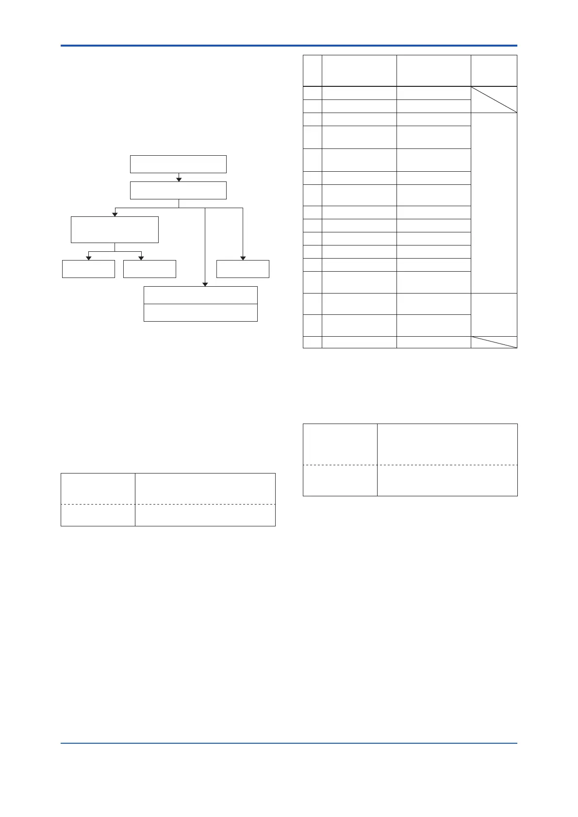
4.2.2.5 Alarm and Alert Setting
The abnormal results as the blockage detection and
high/low ange temperature (heat trace monitoring)
are given through an analog alert or the LCD
display of alarm status. Before performing the ILBD
operation, it is necessary to set the alarm and alert
according to the following procedure.
Storage of Abnormal results
(Diag Error)
Alarm Masking
(Diag Option)
Outside Diagnosis Range/
Invalid Ref xx
Masking
Alarm on
Analog Output
Alarm on
Status Output
Device Status
Field Device More Status Available
Additional Device Status
(Status group 8 and 9)
Alarm Display
on LCD
F0408.ai
Figure4.6 AlarmandAlertSetting
Alarm Status
When the algorithm of ILBD and Heat trace
monitoring detect the abnormality, the result is
stored in Diag Error. The alarm status based on the
detected abnormality is displayed to Diag Error.
(Displayed to Impulse Line Blockage Detection
and Heat Trace for DTM(HART 5))
• Procedure to call up the display
DD and DTM
(excluding EJX_
HART 5[1.2])
[Root Menu] → Diag/Service →
Diag Parameters → Diag Error →
EJX_HART 5[1.2]
DTM
Diag and Service → Advanced Diag
Alerts → Diag Error

 Loading...


