<4. Diagnostics>
4-13
IM 01C25T01-06EN
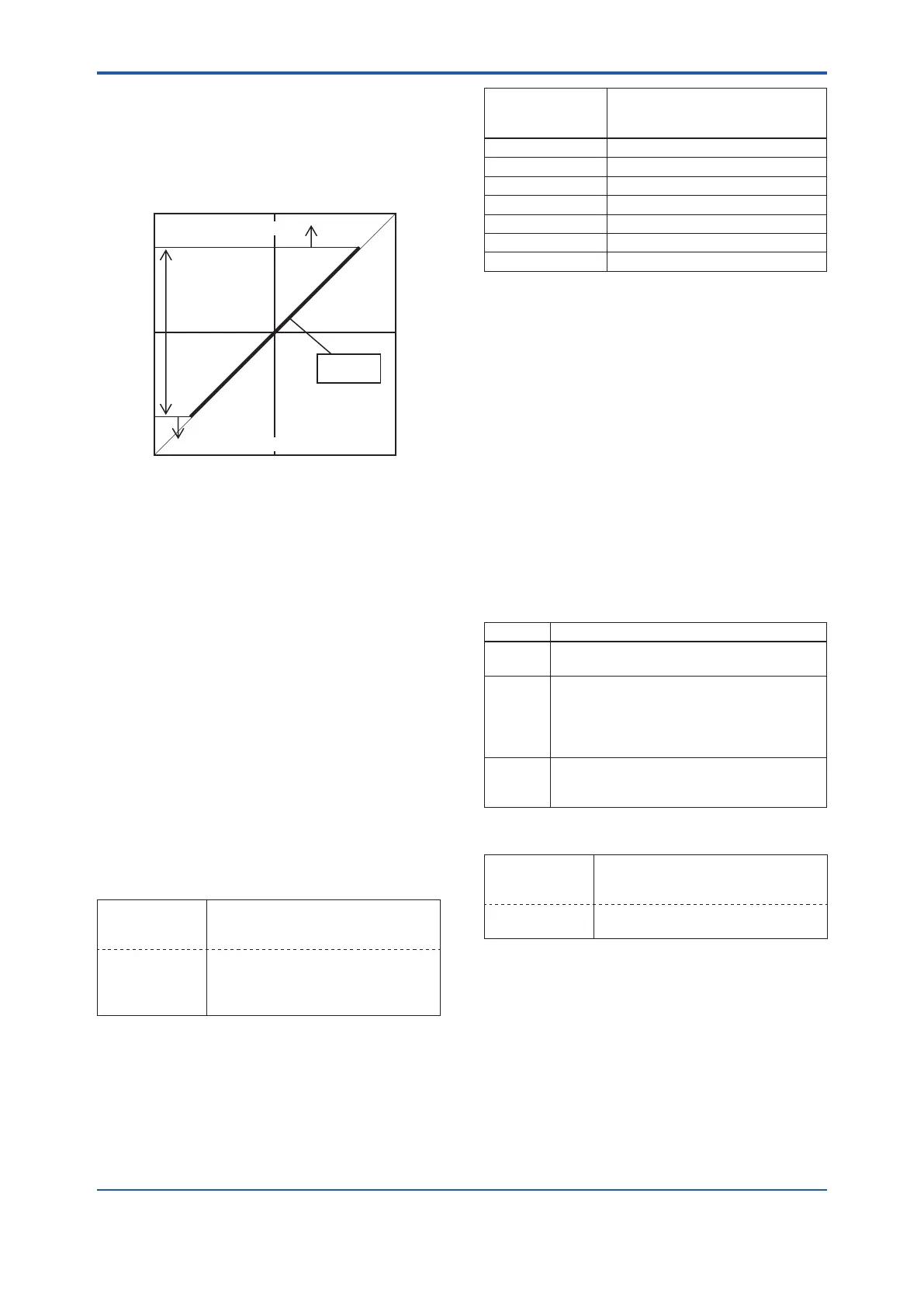
<Example>
When the level range that can be measured by the
transmitter with 100 kPa span is –80 to 80 kPa, the
limits are set as follows.
• Lim DPAvgmax: 0.80
• Lim DPAvgmax: –0.80
0.000
0.80
-0.80
-1.000
Detectable
range
DPAvg
ILBD over range
ILBD over range
F0409.ai
InvalidRefF,SPH,SPL,orDP
This alarm indicates that the reference value under
normal condition is invalid. If RefF is invalid, the
blockage detection excluding BlkF is carried out.
If blockage detection function based on BlkF is
required, obtain the reference value again.
Also when Ref DPAvg is below Lim DPAvgmin
or exceeds Lim DPAvgmax, all reference value
becomes invalid so that “Invalid Ref DP”, “Invalid
Ref SPL”, “Invalid Ref SPH”, and “Invalid Ref F” are
generated.
Alarm Masking
Diag Option
The alarms linked to an analog alert and LCD
display are selected by Diag Option.
• Procedure to call up the display
DD and DTM
(excluding EJX_
HART 5[1.2])
[Root Menu] → Diag/Service → Diag
Parameters → Diag Option →
EJX_HART 5
[1.2] DTM
Diag and Service → Advanced Diag
Congurations → Impulse Line
Blockage Detection → Diag Option
→
The bit of Diag Option is corresponding to that
of Diag Error. The following alarms are set at
the factory setting, which is corresponding to
hexadecimal 0x08FC.
DD
(HART 5/HART 7)
DTM (HART 7)
DTM (HART 5)
A Blocking A Blocking
Large Fluct L Large Fluctuation of Low Side
Large Fluct H Large Fluctuation of High Side
L Side Blocking Low Side Blocking
H Side Blocking High Side Blocking
B Blocking B Blocking
Invalid Ref DP Invalid Ref fDP
To Link the alarm to an analog alert and LCD
display, follow the procedure below.
1) Set “Stop” to Diag Mode.
2) Check each checkbox of the alarm, which is
selectable from bit 2 to 14.
Note: Set to “Calculation” after setting the parameter.
Alert Setting
Diag Out Option
When an alert regarding the impulse line blockage
or high/low ange temperature is generated, the
output value of 4-20 mA analog signal can be
changed.
Mode Function
O
Keeping PV measurement. The alert is not
reected to 4-20 mA analog signal.
Burnout
The analog signal is shifted to the value of
AO upper limit or AO lower limit when an
alert is generated.
The shifted direction follows Burnout switch
setting.
Fall back
The analog signal is hold to the specic
value, DiagFixedOutVal, when an alert is
generated.
• Procedure to call up the display
DD and DTM
(excluding EJX_
HART 5[1.2])
[Root Menu] → Diag/Service →
Diag Parameters → Diag Output →
Diag Out Option →
EJX_HART 5
[1.2] DTM
Diag and Service → Advanced Diag
Congurations → Diag Out Option →
DiagFixedOutVal
This parameter is used when “Fall back” is selected
to Diag Output Option.
When an alert is generated, the 4-20 mA analog
signal is held on the value specied by this
parameter.
The value can be entered within 3.6 to 21.6 mA.

 Loading...


