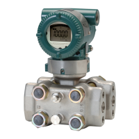
Do you have a question about the YOKOGAWA Dpharp vigilantplant EJA210A and is the answer not in the manual?
Instructions for safe operation and installation of the transmitter.
Details Yokogawa's warranty coverage and conditions for repair.
Information on ATEX Ex related documentation availability in different languages.
How to check the model name and specifications on the transmitter's name plate.
Instructions for safely unpacking the transmitter from its original packaging.
Precautions for storing the transmitter, especially for long periods.
Guidelines for choosing a suitable installation location for stable operation.
Important warnings and precautions related to connecting the transmitter to process pressure.
Procedure for waterproofing cable conduit connections using sealant.
Guidance on potential interference from radio transceivers.
Procedures for performing insulation resistance and dielectric strength tests.
Specific requirements for installing explosion-protected transmitters, including FM, CSA, IECEx, and CENELEC ATEX certifications.
Identifies and illustrates the various components of the transmitter.
Cautions and important notes to consider before and during transmitter installation.
Procedure for mounting the transmitter onto a process using its high-pressure side flange.
How to rotate the transmitter section in 90° segments for optimal positioning.
Instructions for changing the direction of the integral indicator.
Procedure for affixing the FEP Teflon film and fluorinated oil for specific options.
Precautions for installing impulse piping to ensure accurate pressure conveyance.
Examples of typical impulse piping connections for open and closed tank setups.
Important precautions for laying out wiring to avoid electrical noise and ensure safety.
Guidelines for selecting appropriate wires and cables based on environmental conditions.
Procedures for connecting external wiring, including power supply and indicator connections.
Details on loop configuration and wiring installation for different transmitter types.
Requirements and procedures for proper grounding of the transmitter.
Guidance on selecting appropriate power supply voltage and load resistance for the loop.
Steps to prepare the transmitter for starting operation, including checks and BT200 connection.
Procedures for adjusting the zero point using the transmitter screw or BT200.
Procedure for starting transmitter operation after zero point adjustment.
Instructions for safely shutting down the transmitter.
How to vent gas or drain condensate from the pressure-detector section.
How to re-range the transmitter's low and high limits using the integral indicator.
Precautions for connecting and using the BT200 terminal.
Detailed explanation of BT200 keypad layout, screen display, and key functions.
Procedures for setting various transmitter parameters using the BT200.
How to display measured data, model, and specifications using the BT200.
How to check for problems and understand error messages using the BT200 or integral indicator.
Introduction to maintenance procedures, emphasizing careful handling.
Identification of instruments required for accurate calibration.
Procedure for checking instrument operation and accuracy through calibration.
Step-by-step procedures for disassembling and reassembling the transmitter for component replacement.
Flow charts and basic steps to isolate and remedy measurement system problems.
Lists standard performance and functional specifications of the transmitter.
Explains how model and suffix codes define transmitter configurations.
Details on optional specifications, particularly explosion-protected types.
Provides dimensional drawings and tables for the transmitter.
| Model | EJA210A |
|---|---|
| Category | Transmitter |
| Manufacturer | YOKOGAWA |
| General Use | Differential Pressure Measurement |
| Communication Protocol | HART |
| Process Temperature Limits | -40 to 120°C (-40 to 248°F) |
| Output Signal | 4 to 20 mA DC |
| Stability | ±0.1% of URL per 10 years |
| Ambient Temperature Limits | -40 to 85 °C |
| Enclosure Rating | IP66 |
| Process Connection | 1/2 NPT |
| Certifications | ATEX, IECEx, CSA, FM |


