Do you have a question about the YOKOGAWA mR10000 436101 and is the answer not in the manual?
General safety advice and standards compliance for recorder operation.
Guidance on interpreting manual symbols, warnings, and structure.
Instructions for safely unpacking the recorder and its components.
Details manual coverage for different recorder versions and their functions.
Monitors measured values for high/low limits with optional relay outputs.
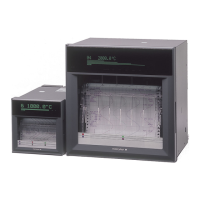
Records measured values on chart paper with selectable speeds and print options.
Shows measured values numerically or via bar graphs, including alarm status.
Enables data output and control via Ethernet or RS-422A/485 interfaces.
Describes computation, remote control, and fail/chart end detection features.
Identifies the physical components located on the recorder's front panel.
Identifies the physical components located on the recorder's rear panel.
Explains the indicators (RECORD, KEY LOCK, MATH, etc.) on the status display.
Details the function of each key for operation and setting modes.
Specifies suitable environments and conditions for recorder installation.
Illustrates the process of mounting the recorder to a panel using brackets.
Details safe and accurate input signal connections, including noise prevention.
Instructions for connecting optional interfaces and relays like alarms.
Guides on connecting the recorder to power, covering panel and portable types.
Describes Operation, Setting, and Basic Setting modes of the recorder.
Explains how to navigate menus and select items using the recorder's keys.
Procedures for inputting numerical values and text characters.
Hierarchical view of the options and functions available in Setting mode.
Hierarchical view of the options and functions available in Basic Setting mode.
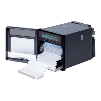
Instructions for loading and replacing the chart paper in the recorder.
Procedures for replacing felt pens and ribbon cassettes.
How to view and adjust the recorder's internal clock.
Example for setting thermocouple type K input and recording range.
Example for setting 1-5V input and scaling parameters.
Example for setting 0-10V input and converting units using scaling.
Configuring alarm levels, types (high/low limit), and values for channels.
Defines different alarm types like High/Low Limit, Rate-of-Change, and Delay.
How to initiate and end the recording process using the RCD key.
Adjusting the chart paper feed rate via the Setting mode.
How to access and view the recorded chart paper for analysis.
Explains specific printout types: manual, periodic, alarm, message, and start.
Navigating through different display formats using the DISP key.
Procedure to select and register desired display types for screens.
How to print current measured values and alarm statuses.
How to print list and setup configurations of the recorder.
Erasing buffered alarm and message print data from memory.
Releasing alarms and managing the key lock function.
Default values for parameters configurable in Setting mode.
Default values for parameters configurable in Basic Setting mode.
Default values for RS-422/485 and Ethernet communication settings.
Recommended replacement intervals for worn parts in the pen model.
Recommended replacement intervals for worn parts in the dot model.
| Power Supply | 100 to 240 V AC, 50/60 Hz |
|---|---|
| Operating Temperature | 0 to 50 °C |
| Display Type | LCD |
| Recording Media | SD card |
| Communication Interfaces | Ethernet |
| Accuracy | ±0.1% |