1-1
SM MV1000-01E
Principles of Operation
Chapter 1 Principles of Operation
1.1 Principles of Operation
The following explains the principles of operation of the MV.
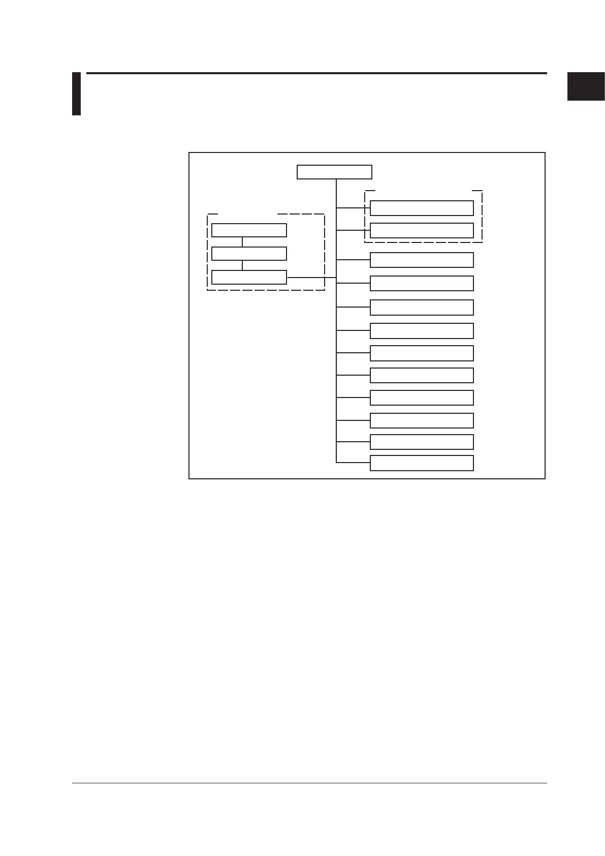
Block Diagram
Data storage functions
Input section
Calculation function
Alarm
Communication function
(optional)
Input terminal
Scanner
A/D
CPU
External storage
Internal memory
Display
Remote control
Relay contact
(optional)
(optional)
Pulse input
Transmitter power supply
(optional)
USB port
Key
Input Terminal Section
For connecting the measurement input signal wires. The terminals can be used for DC
voltage, thermocouple, resistance temperature measurement, and contact input.
•
The reference junction compensation circuit for thermocouples is built in.
• Proven transistor method for measuring the temperature of the terminals.
• Metal core construction used in the internal printed circuit boards to equalize
temperature.
•
Input terminals removable.
Scanner Section
Switches the measured input signal (channel). The input signal switching section uses
highly reliable solid state relays (SSR).
A/D Conversion Section
Converts analog signals to digital signals. It is a PWM (pulse width modulation) type
converter. A/D converter calibration data is stored in an EEPROM.
For the correspondence between input channels and A/D converters, see “Measurement
Accuracy” on page 3-6.
 Loading...
