General Instruction Manual
Wiring
Transmitter
62 / 90
IM 01U10B00-00EN-R, 3rd edition, 2018-07-09
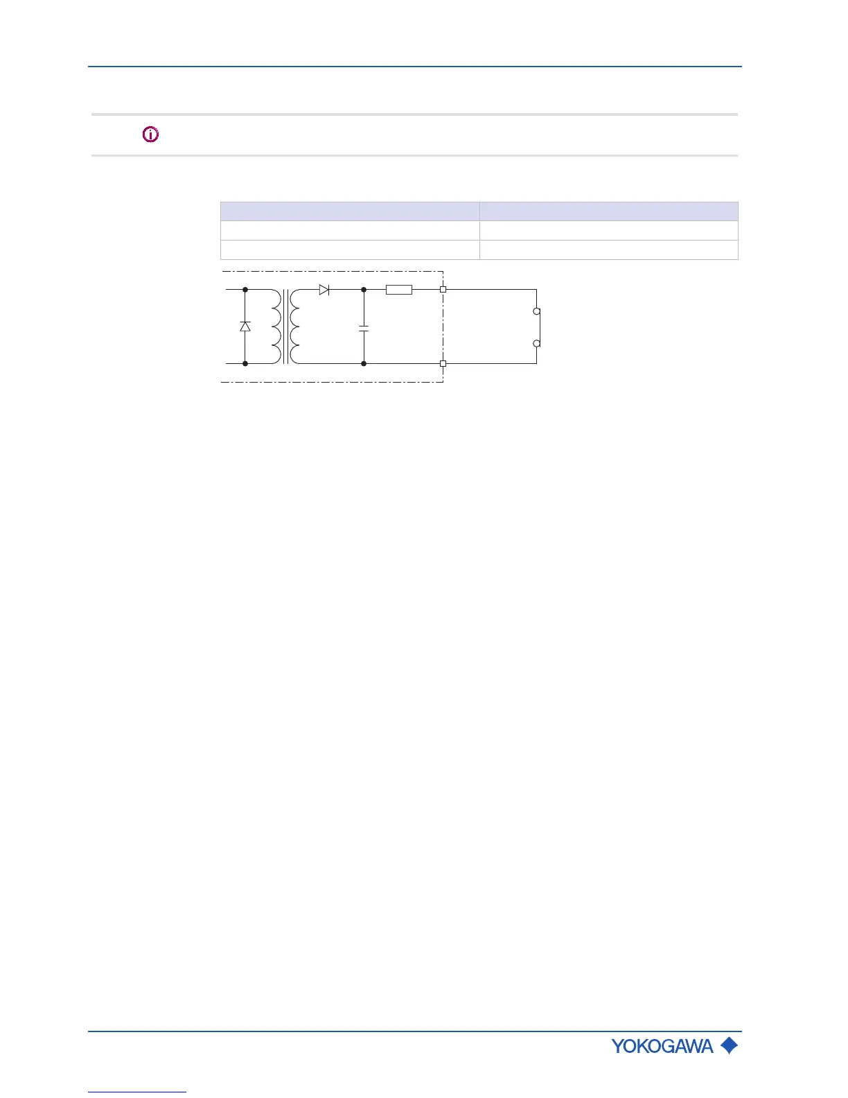
Status input Sin
Do not connect a signal source with electric voltage.
The status input is provided for use of voltage-free contacts with the following specifica-
tion:
Switching status Resistance
Closed < 200 Ω
Open > 100 kΩ
Fig.53: Status input connection
7.4.7 Power supply
Power supply
Alternating-current voltage (rms):
▪ Power supply
1)
: 24 V
AC
+20 % -15 % or 100–240 V
AC
+10 % -20 %
▪ Power frequency: 47–63Hz
Direct-current voltage:
▪ Power supply
1)
: 24 V
DC
+20 % -15 % or 100–120 V
DC
+8,3 % -10 %
1)
for option MC␣ (DNV GL approval) supply voltage is limited to 24 V
Power consumption
P ≤ 10 W (including sensor)
Power supply
failure
In the event of a power failure, the flow meter data are backed up on a non-volatile inter-
nal memory. In case of devices with display, the characteristic sensor values, such as
nominal diameter, serial number, calibration constants, zero point, etc. and the error his-
tory are also stored on a microSD card.
 Loading...